|
SmartPick is an intuitive, easy-to-use tool designed to make all your
Sketcher creation and edition tasks as simple as possible. SmartPick
dynamically detects the following geometrical constraints:
- support lines and circles
- alignment
- parallelism
- perpendicularity
- tangency
- concentricity
- horizontality and verticality
- midpoint
What are Constraints?
There are times when simple sketches are adequate for your design
process, but you will often need to work on more complex sketches requiring
a rich set of geometrical or dimensional constraints. The Sketcher
workbench provides constraint commands which will allow you to fully sketch
your profiles. |

|
When you apply constraint on curves, lines, circles and ellipses, the
complete geometrical support is taken into account.
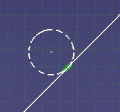
As an example for this arc, the entire circle is taken into account when
you apply constraints.
|

|
The location you click when selecting the elements to constrain is
taken into account to create the constraints (it is used to position the
constraints accurately). Therefore, when selecting the elements to
constrain, it is important that you click where you want the constraint to
be positioned. The software will then position the constraint according to
the area where you clicked.
This is especially true when creating constraints on certain types of
curves (complex curves like splines, for example). In some cases, if you
don't click in the right place when selecting the curve to constrain, the
constraint and the geometry will be inconsistent. |
|
Geometrical Constraints
A geometrical constraint is a relationship that forces a
limitation between one or more geometric elements. For example, a
geometrical constraint might require that two lines be parallel. If you
select three lines, or two lines and a point, these elements will
automatically result parallel to each others, as illustrated in the table
further down.
You can set a constraint on one element or between two or more elements. |
| |
Hiding or Showing Constraints
Three existing settings are available from the Visualization
toolbar. They all let you adjust the visualization of constraints according
to your needs. You can hide:
- constraint diagnoses just by deselecting the Diagnosis
 icon
icon
- dimensional constraints just by deselecting the Dimensional
Constraints
 icon. icon.
- geometrical constraints just by deselecting the Geometrical
Constraints
 icon icon
To know more about these capabilities, refer to the Filter paragraph in
Symbols.
|

|
The visualization mode of constraints is based on the 3D constraints
visualization filter.
The constraints visualization filter settings applied while editing a
sketch are specific to this sketch and prevail over the settings defined
in the 3D constraints visualization filter (Tools> Options> Parameters
and Measure> Constraints and Dimensions> Filter).
These specific settings will be kept every time the sketch is edited. |
|
What About Constraint Colors?
|
| |
As soon as you detect a
constraint problem, try to solve this problem. Otherwise, if you let
the model be overloaded with diagnostics, it will soon become very hard for
you to find the origin for each of these diagnostics. For more
information about over-defined or inconsistent sketches, see
Analyzing and Resolving over-defined or
inconsistent Sketches. |
| |
COLOR and DIAGNOSTIC |
SOLUTION: |
| |
|
|
| |
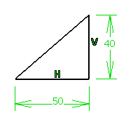
White: Under-Constrained Element |
| |
The geometry has been
constrained: all the relevant dimensions are satisfied but there are still
some degrees of freedom remaining. |
Add constraints. |
| |
 |
 |
| |
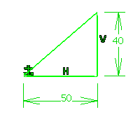
Brown: Element Not
Changed |
| |
- Some geometrical elements are over-defined or not-consistent,
- or the geometry is fixed,
- or there is either two free or one free and one
fixed geometry in the same set.
As a result, geometry that depends on the problematic area will not be
recalculated. |
Remove one or more dimensional constraints, or, in the
case of fixed geometry, unfix it. |
| |
 |
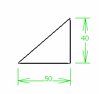
|
| |
Green: Fixed Element |
| |
The geometry has been fixed
using the Constraint Definition dialog box or the contextual menu (right
mouse button). |
|
| |
 |
|
| |
Green: Iso-Constrained
Element |
| |
All the relevant dimensions
are satisfied. The geometry is fixed and cannot be moved from its
geometrical support. |
|
| |
Geometry before and
after being moved: |
|
| |
 |
 |
|
| |
|
|
|
| |
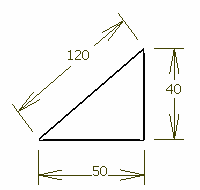
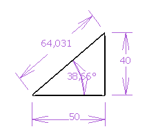
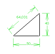
Purple:
Over-Constrained Element |
| |
The dimensioning scheme is
over-constrained: too many dimensions were applied to the geometry. |
Remove one or more dimensional constraints. |
| |
 |
|
| |
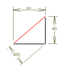
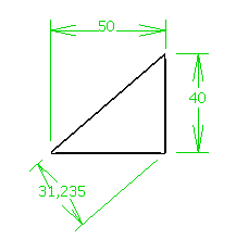
Red: Inconsistent
Element |
| |
At least one dimension value
needs to be changed. This is also the case when elements are
under-constrained and the system proposes defaults that do not lead to a
solution. |
Add dimensions. Set dimension value(s) properly. |
| |
 |
 |
 |
Inconsistent and Over-Constrained Elements
If a sketch contains inconsistent and over-constrained elements when
leaving the Sketcher workbench a warning will be generated . |
|
|
Under-Constrained Elements
If a sketch is under-constrained when leaving the Sketcher
workbench, the application generates errors if Generate update errors
when the sketch is under-constrained is active. For more information,
refer to the section describing how to customize your Sketcher session and
more precisely, see
Update. |
|
Creating a Constraint Between a 2D and a 3D Element
When you need to create a constraint between a 3D element and a line,
for example, this creation may result impossible. This is the case when the
projection or intersection resulting use-edge does not give a unique
solution. In other words, the use-edge (projection of one side of a pad)
corresponds to several limit edges of the side.
As a result, you will not be able to select this 3D element when
creating the constraint. You will therefore have to use manually the
projection operators. |


