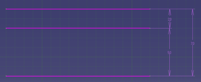
If all of the degrees of freedom of a geometry have been taken up by a consistent combination of dimensions and fixed geometry, that geometry is said to be iso-constrained (also known as well-defined). Geometry that still has some degrees of freedom is said to be under-constrained (also known as under-defined).
Status codes are given through a graphical way (colors) during the Sketch edition. The update error dialog box when returning in 3D explicitly gives them (check visualization of diagnosis in Tools > Options > Sketcher > Colors).
Note that:
- The system will mark all entities that are relevant to a problem rather than just the first item encountered. So, for instance, in the case of an inconsistent triangle with sides 10, 10 and 50, all three dimensions would be marked as INCONSISTENT.
- The order in which the codes are listed below is significant. The system will test to see whether a geometry should have the status OVER-CONSTRAINED before considering whether it should be INCONSISTENT.
This chapter describes the over-constrained and inconsistent status codes calculated by the system and explain methods for solving any underlying problems with a Sketch.
Over-constrained
In many sketches, the user will specify more than the minimum required number of dimensions or constraints. In certain cases the system will ignore redundant constraints and solve the Sketch. In other cases it will mark parts of the Sketch as over-constrained.
The descriptions below refer to consistent constraints and dimensions. Dimensions are said to be consistent if their values are satisfied by the position of the geometries.
Geometry will be marked as over-constrained when it cannot be solved because there are too many dimensions acting on it for the degrees of freedom available.
A dimension will be marked as over-dimensioned if it conflicts with one or more other dimensions and it is not possible to vary the value of the dimension and still find a consistent solution. For example, the geometry and dimensions in the figure below will be over-constrained because the dimension values cannot be varied independently, even though they can all be satisfied by appropriate geometry positions.

The following is a list of some of the over-constrained configurations that can be solved:
- Multiple constraints between the same geometries.
For instance, two circles can have several tangent constraints between them. - Multiple coincident constraints between geometries of the same type.
For instance, three points can each be made coincident to the other two. - Multiple coincident constraints between lines and points.
For instance, two lines can be made coincident, and their endpoints can be made coincident with the other line.
Parallel and perpendicular constraints. Any combination of parallel and perpendicular constraints will be reduced to the minimum set required, and any excess ones will be ignored. Note that a distance dimension between two lines is treated as a parallel constraint, except that it will never be one of the constraints that is ignored.
Symmetric constraints . There are many configurations where symmetric constraints will make other constraints redundant. These are recognized by the system. For example, if two lines are made symmetric two of the coincidence constraints between the points and the lines are redundant.
Resolving Over-constrained Cases
Over-constrained entities occur in loops where all of the entities in a loop conflict with each other.
Over-constrained entities can also occur when there are too many fixed geometries.
To resolve over-constrained problems, the user will need to:
- Set as references dimensions
- Deactivate or remove constraints
- Unfix geometry
Note that the system will evaluate as much of the geometry as possible. It determines exactly which dimensions are contributing to the situation.
Inconsistent
This section describes when the inconsistent status codes can occur and how you can modify the Sketch to avoid them.
In general, the inconsistent status shows that the user is attempting to make a change to the Sketch that is too large. In this context, "large" is relative to the size of the Sketch.
Parts of a Sketch may become inconsistent as a result of a number of different operations.
The most common of these are as follows:
- The user changes the value of a dimension. This will normally occur for cases where there would be large changes to one or more geometries.
- The user adds a dimension or constraint to a Sketch, in order to move geometry.
- When dragging geometries, the user attempts to input a large transformation.
- When the geometric type of a use-edge is changed (geometry coming from the projection or intersection of a 3D geometry)
- When there are use-edge large positions or orientations changes.
- When an element of a geometry is deleted (especially in conic
curves, connecting curves, spline offsets).
The geometry has not been solved because:
- No solution exists for the current values of dimensions.
- The system cannot find a solution, even though a solution may exist with the current values of dimensions. This occurs when trying to make large changes to under-constrained sketches or to parametric curves (See section Over-constrained and Inconsistent on Parametric Curves below for further details).
- The system has not find a solution that respects the previous chirality.
Chirality determines the way that geometry is positioned relative to the
geometries to which it is dimensioned. A dimensioning scheme can often be
satisfied by a number of different configurations. The system will always
evaluate a new configuration that has the same chirality as the original
geometry. It is important to realize that geometry in the system always has
an original configuration, which is used for deciding the chirality.
Resolving Inconsistent Cases
If the inconsistent status code was a result of changing a dimension value, the problem will be resolved by changing the dimension back to its old value. However, in some cases the user may want to modify other parts of the Sketch to allow the change to be made. The following sections describe different ways that can be tried.
When attempting to solve a problem, the user should focus on the geometries and dimensions in the Sketch with the inconsistent status code.
In order to decide how to avoid the status code it is useful to check first if the problem comes from inconsistent dimensions.
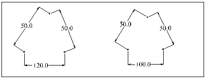
An example of this is a triangle with sides of length 50, 50 and 120.

Not Changed
- When geometry becomes over-constrained or inconsistent, the system will not be able to position any other geometries that depend on it. These dependent geometries and their associated dimensions (and any others that depend on them) will be marked not changed.
- Dimensions between two fixed geometry will be given the status code not changed.
- Dimension between two free or one free and one fixed geometry in the same set will be given the status code not changed.
Parametric Curves
This section is an overview of specific over-constrained and inconsistent problems on parametric curves. The Sketcher can manipulate points, lines, circles and ellipses but can also manage splines and nurbs.
These parametric curves can be created:
- Through an Intersection or Projection of a 3D geometry in the Sketch. After isolating it, constraint can be used to change the position of the curve. The system is unable to directly modify the shape because the curve, which have no internal freedoms that the system can control, have only three degrees of freedom.
- By the Spline command. The curve is defined from other geometries. The parametric curve is said dependent. It is constructed so it passes through a series of control points.
Constraints and dimensions can be added between a dependent parametric curve and other geometries in the sketch.
Solving problems will occur:
- If the position of the defining geometry depends upon the position of the parametric curve, either directly or indirectly.
- When the other geometry of the constraint or dimension is an other parametric curve or dependent parametric curve.
Always use the Constraint command without dialog box to specify where the constraint must be created on the curve . Through the Constraint Defines in Dialog Box command, the selection points are not taken into account.
On fully under-constrained sketches, the system can have difficulty choosing between changing the shape and/or moving its defining geometry especially when it supposes to make large changes. Moving the geometry will help the system find a consistent solution in that case.