 |
This task shows you how to align a cloud of points with a reference with RPS.
This command is mainly
intended for parts digitized using RPS.Differences between aligning with
constraints and aligning with RPS
Similarly to alignment with constraints, RPS alignment is defined by a
set of constraints.
The differences between these two alignment commands
are:
| Align with RPS |
Align with Constraints |
A well-defined RPS alignment must always be isostatic,
to insure the repeatability of alignment conditions. |
Non-isostatic system is accepted. |
| Constraints are defined only by points, circles and
arcs. |
Constraints can also be defined by planes,
cylinders and spheres. |
When a circle or an arc is input,
its center position, i.e. a point, is taken into account |
When a circle or an arc is input,
its center axis, i.e. a line, is taken into account |
| Only translations can be frozen. |
Translations and rotations can be frozen. |
| For each RPS constraint, at least one axis must be
frozen. |
|
In a point - point constraint, you can freeze one,
two
or three axes of the point on the reference. |
In a point - point constraint, all the three axes (X, Y
and Z)
of the point on the reference are automatically frozen. |
Definition of a RPS Alignment
Since a RPS alignment is isostatic, the following conditions must be
satisfied:
- In a first axis, three RPS constraints must be frozen to define a
plane.
- In a second axis, two RPS constraints must be frozen to define a line.
- In a third axis, one RPS constraint must be frozen to define the
locating point.
Defining a RPS alignment requires a minimum of 3 RPS constraints and a
maximum of 6 RPS constraints. |

|
-
Select the Geometrical Set where you want to create the
output cloud, if any, and select Define In Work Object.
-
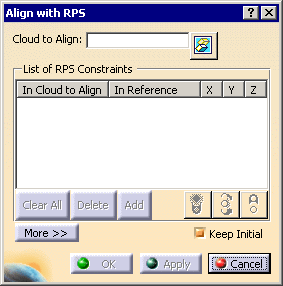
Click Align with RPS
 in the Reposit toolbar.

-
Select the
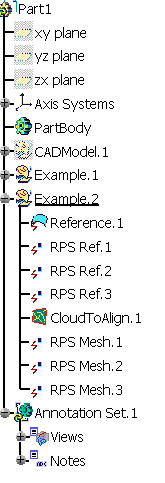
Cloud to Align (we have selected CloudToAlign.1
in Example.1). The Cloud to Align can be a cloud of points or a mesh.
Once the
Cloud to Align is selected, the button
Add becomes
available.
-
Define a first constraint:
-
Click Add.
-
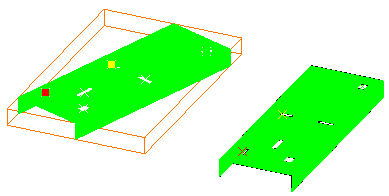
Select the point RPS Mesh.1 on the Cloud to Align then the point
RPS Ref.1 on the
reference.
-
The dialog box is updated.

Both points are highlighted in red.
-
In the dialog box, place your cursor on the line of this constraint
and click under X, Y, Z to freeze those axes.

If needed, click again on X, Y or Z to unfreeze an axis.
The light is still yellow meaning there is not enough constraints to
define the RPS alignment.
|
-
Define a second constraint with points RPS Mesh.2 and
RPS
Ref.2 and frozen axes X and Y
then a third constraint with points RPS Mesh.6 and
RPS Ref.6 and frozen
axis Y.
-
The light has turned green, meaning that the RPS
alignment is correctly defined.
 |
- The light is yellow when there are too few or too many
constraints to define the RPS alignment, i.e. the alignment is not
fully defined.
- The light is green when the RPS alignment is fully defined and
the alignment result is isostatic.
- The light is red when the RPS alignment is fully defined but the
alignment result is not isostatic.
|
-
|
|
|
 |
|
-
Click Apply to start the alignment.
-
The Cloud to Align is moved towards the reference.

-
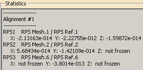
Click More to display the
Statistics.

Alignment #1 indicates this is the first computation you
have launched since you have opened the dialog box,
For each constraint (e.g.
RPS1) is given:
- the name of the constraint elements selected
RPS Mesh.1/RPS
Ref.1
- the distance (X: -2.13163e-014) between the constraint element on
the Cloud to Align and the constraint element on the reference along the
frozen axes. not frozen means that the corresponding axis is
not frozen.
|
-
Once you are satisfied, click OK to validate and exit the
dialog box.
-
-
-

-

|
In both cases, an Axis Systems is created with::
- AxisTrs.x (system axis computed on the Cloud to Align) and
- AxisRef.x (axis system created on the output cloud).
|
 |
Those Axis Systems can be used with the
Axis
to Axis action on other elements to align.
Align with previous transformation is
also available. |
|