 |
This task shows you how to align clouds of points (clouds to
align) to other clouds of points (reference),
using sphere recognition. |
 |
See the glossary for the
definition of Cloud to Align, reference, constraint and constraint element. |
 |
Open the
Reposition1.CATPart model the from the samples directory.
It consists of two clouds of points with three spherical tags on each.
These tags have been created during digitizing in order to align the two
clouds in future operations. |
 |
-
Select the Geometrical Set where you want to create the
output cloud, if any, and select Define In Work Object.
-
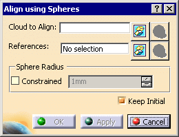
Click Align using Spheres
 in the Reposit toolbar.

-
Select the Cloud to Align (we have selected
Cloud Import.1).
Its name is displayed in the
dialog box and it is highlighted in the 3D Viewer.
-
Select the
References (we have selected
CloudImport.2)
|
 |
|
|
|
-

- If you know the radius of the spheres, check
the Constrained
check box and type the radius in the input field.
Align using Spheres will compute the spheres with that radius.
- If you do not know the radius of the spheres,
click the first sphere.
Align using Spheres will compute this radius and update the input
field accordingly.
Then you can select the Constrained
check box and select other spheres
that will have the same radius.
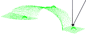
- We recommend that you pick the sphere in a direction orthogonal to the
part to process,
i.e. along the green axis and not along the black axis in our example:

-
For an easier sphere recognition, we recommend that you
pick in the middle of the sphere, not at the edge.
-
If you use 3 spheres, they should not form a isosceles nor
an equilateral triangle
(the system could not find out the right solution between the two or six
possible solutions).
|
-
|
|
|
 |
|
-
Click Apply. The Cloud to Align is
aligned with the References.
-
Once you are satisfied with the alignment, click OK to
validate it and exit the dialog box.
-
In both cases, an Axis Systems is created with:
- AxisRef.x (system axis computed on the Cloud to Align) and
- AxisTrs.x (axis system created on the output cloud).

Those Axis Systems can be used with the
Axis
to Axis action on other elements to align.
Align with previous transformation is
also available.
|
|
 |
- While aligning clouds, you can use the function
Distance analysis to check the output accuracy.
The target will be the output cloud. Since a new output cloud is generated
at each alignment,
you should repeat the distance analysis with each new output cloud.
- The result entity has the same structure as the input entity: scans,
grids or meshes.
- Undo is available on the selection of spheres.
|
|

|
 in the Reposit toolbar.


![]()

