-
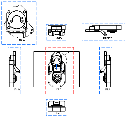
Create a front view of the part.
-
Create a right, left, bottom and top projection view.
-
Then create an auxiliary view of the top view.
-
Create a detail view on the front view.
-
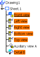
In the specification tree, right click and select Front view object> Modify Projection plane.
The front view and all the projection views are highlighted, showing that the modification will impact all the views.
-
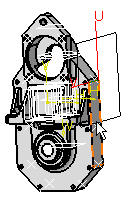
Select an edge of the part as your new reference plane.
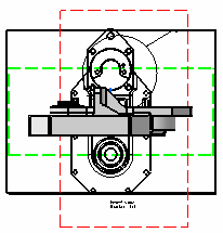
The front view with the new reference plane is previewed in the drawing.
-
Click on the drawing sheet to create the front view according to the reference plane you selected.
The front view is updated and, in the specification tree, each projection view appears as needing an update.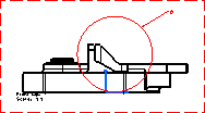
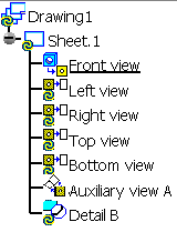

- The update is made in two steps: first the front view, then the views linked to the front view, that is, the projection views and the detail view.
- You will note that the detail view callout has become red because there is an inconsistency between the referring view and the detail view.
-
Right-click on each projection view and select Update selection in the contextual menu to update the view according to the new reference plane.
Or right click on Drawing1 and select Update selection in the contextual menu.
The right, left, bottom, top and auxiliary views are updated, as well as the detail view. The detail view callout turns black again since there is no inconsistency left.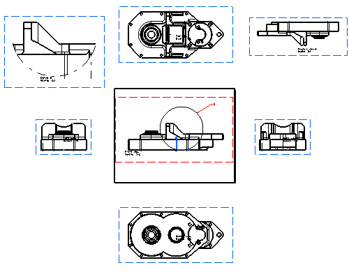
- top, bottom, right, left, auxiliary, detail,
- locked,
- isolated,
- interactive
You cannot propagate the modification of a projection plane on a section
or auxiliary view created from the Auxiliary view icon.
You have to recreate them in order to take into account the new reference
plane.
- isometric views.
-
Create an isometric view of the part.
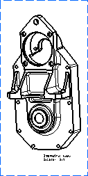
-
Modify the part position.
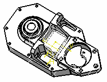
-
Right-click the view and select Isometric view object > Modify Projection plane.
-
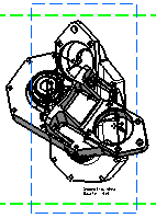
Click on the part.
The isometric view with the new reference plane is previewed in the drawing.
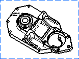
The isometric view is modified in the drawing.
For more information on dress-up elements, refer to the Dress-Up Elements section and the Modifying a Callout Geometry section.
![]()