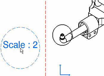
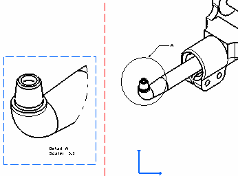
A detail view is a partial generated view that shows only what is necessary in the clear description of the object. Note that the Detail View command uses a boolean operator from the 3D whereas the Quick Detail View command computes the view directly from the 2D projection. The representation is therefore different.
-
In the Drawing window, click Detail View
 in the Views toolbar (Details sub-toolbar). You
will create a circular detail view.
in the Views toolbar (Details sub-toolbar). You
will create a circular detail view.To create a detail view using a sketched profile, click Detail View Profile
 .
. -
Click the callout center.
If you are creating a detail view using a sketched profile, create the required points for sketching a polygon.
-
Drag to select the callout radius and click a point to end the selection.
If you are creating a detail view using a sketched profile, double click to end the cutting profile creation. Note that if you do not close the profile, it will be closed automatically.


The dress-up elements generated from the 3D are identified and represented in the generated detail view whereas it is not when generating quick detail views. -
Click to generate the detail view.
The default scale is 2 (twice the scale of the active view). You will now modify this scale in the Properties dialog box.
-
Right-click the detail view, select Properties and then the View tab.
-
Enter the desired Parameters Scale, for example 3.
-
Click OK to validate and exit the Properties dialog box.

- You can also modify the detail view profile through the Properties dialog box.
- You can assign a line type to the view to be generated. To do this, go to Tools > Options > Mechanical Design > Drafting > View tab, click the Configure button next to View Linetype and select the desired option from the dialog box.
- In the isometric view, you can move the detail text ("A" in this example) after detail view creation.
- If you create a detail view from a section view and subsequently modify the cutting profile in the section view, in such a way that the detail view is no longer accurate, the detail view cannot be updated so as to take into account the changes in the cutting profile.
- If you create a broken view from a view which contains a detail view callout, the detail view callout will not be broken in the broken view. In other words, the circular shape of the callout will not be modified, even if the callout overlaps the break profile. As for the detail view, it will not modified by the break operation.
- From V5 R17, when creating a circular detail view, the leader associated to the callout remains perpendicular to the circle. The leader anchor point moves all around the circle to keep this perpendicular orientation. Circular callouts created before R17 are not changed.
![]()