Vibration Volume functionality:
lets you calculate the dynamic envelope of a part or a group of parts with respect to a positions file (Adams or vda or from a Fitting track.
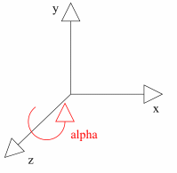
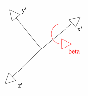
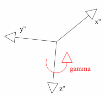
- This dynamic envelope is in fact given by a set of positions in Euler coordinates (in degrees) from an ASCII positions file (ADAMS format or vda format)
- Vibration volume as most Optimizer commands is a multi-selection command, which means the user can select as many input products he wants and then launch the process to the select product or group of products
- Once the computation is launched, a solid shape is generated: this shape represents an envelope of the products (s) placed in every position
- The result can be saved in CGR, VRML, V4 model or STL
Alternate Shape
-
(Optional)
You can manage automatically your result as alternate shape of the initial component.
For this:- Select Tools > Options from the menu bar.
The Options dialog box is displayed. - Expand the Digital Mockup category from the left-hand tree.
- Select DMU Optimizer item to display the corresponding tab. The Alternate Shapes Management is available
- Check Vibration Volume option: it is automatically activated as an alternate shape. When activated the vibration volume representation is the one visualized in session.

Note: If your are not working in alternate shape mode, it is strongly recommended to use the Reference Product option to avoid positioning problems when reinserting products. read About Reference Product
- Select Tools > Options from the menu bar.
-
Click the Vibration volume icon
 from the DMU
Optimizer toolbar.
The Vibration Volume dialog box is displayed: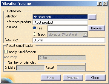
-
Select the product or the group of products on which you want to apply the vibration volume.
In our example, select Mobile Phone in the specification tree 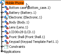
-
Click Browse to select a positions file of your choice.
Two positions files are provided:
You can find them in
C:\Program
       Files\Dassault
       Systemes\B17doc\online\dmoug\samples
folder -
The File Selection dialog box appears:
-
Select the positions file of your choice Adams_4pos.txt and click Open.
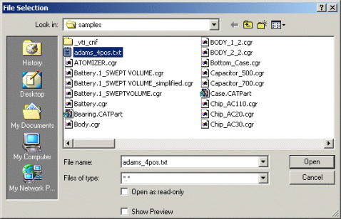
-
The path is updated accordingly in the Positions file field.
-
Set the vibration volume accuracy. In our example, enter 1mm
Setting the vibration volume accuracy
The accuracy determines the precision of the vibration volume representation. The accuracy parameter determines the size of the triangles used to represent the vibration volume. A lower setting results in slower computation time, but a more precise calculation of the vibration volume.
For more detailed information, please see More about Vibration Volume
-
Select the Apply Simplification check box and set the simplification accuracy as you wish (enter 0.5mm)
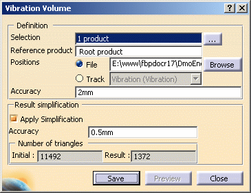

Note: you can also apply the simplification afterwards or launch the operation again with different accuracy values as many times as needed -
Click Preview to launch the calculation and obtain a preview. The progress bar is displayed letting you monitor and interrupt if necessary (Cancel option) the calculation.

The preview window lets you see the resulting vibration volume. 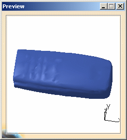

If you are not satisfied with the result, you can simplify the vibration volume result again. For more detailed information, read Using Simplification Command and More about Simplification -
Click Save. The Save As dialog box is displayed.
- Set the Type to .cgr
- Identify the folder in which you want to save the file
- Enter a file name

you can also save your result as a V4 model, .stl or .wrl documents. Also read About Saving Operations 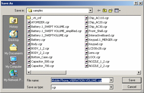
-
Click Save.
 |
![]()
