Special case of zones group used for the creation of solid from zones
To make the definition of zone from plies easier, we propose you
to define zones and transition zones as described in the example below:
With such a ply design

the zone definition will be

and the transition zone will be

The taper will then be created on the area of the ply staggering,
will be associated to the zone with the lowest thickness and
will ensure the connectivity between the zones.
You can then use the Solid From Zones command to
generated the top surface from zones.
This functionality is accessible through the
For Solid From
Zones Creation Only check box.
- those zones created from plies do not correspond to a preliminary design of the Composites part, even if they use a similar data structure.
- they are only created to generate a top surface,
- they are created in a dedicated zones group, marked (For Solid From Zones Creation Only),
- they can only be used in the Solid From Zones and the Connection Generator commands,
- they will be ignored by other commands.
![]()
-
Click Zones Group
 . The
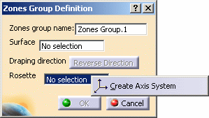
Zones Group Definition dialog box is displayed.
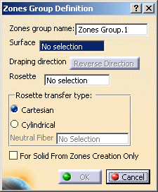
A name is proposed by default for the zones group that you can modify. -
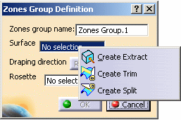
Select the surface on which the zones will be created.
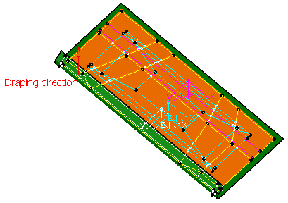
The draping direction is displayed in the 3D geometry.
Click Reverse Direction to inverse its direction.
-
Define the Rosette, that is the axis (X, Y, Z) in which the directions are referenced.
-
If necessary, select the type of rosette transfer to be applied in Producibility, Producibility Inspection or Fiber Direction:
- Cartesian: this rosette transfer type is suitable for panels with a low curvature.
-
Cylindrical: this rosette transfer type is suitable for
parts with a high curvature.
This mode requires that you select a Neutral Fiber, i.e. the axis of the cylindrical shape to be used. The X-axis of the rosette will correspond to this neutral fiber.
-
If necessary, select the For Solid From Zones Creation Only check box.
-
Click OK to create the zones group.
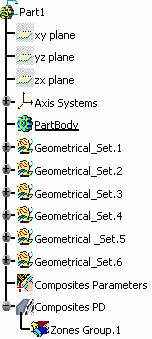
The feature (identified as Zones Group.xxx) is added to the specification tree, under the Composites PD node.
This node will contain the structure for all the defined zones. -
Perform this scenario as many times as you need to create zones groups.
In our scenario, we created two zones groups.
 |
 |
Refer to Generative Shape Design & Optimizer User's Guide for more information.
![]()