![]()
-
Click Zones
 .
.
In case you did not previously create a zone group, an information message is issued prompting you to create one.
Click OK to start the Zone Group Definition command.The Zone Definition dialog box is displayed.
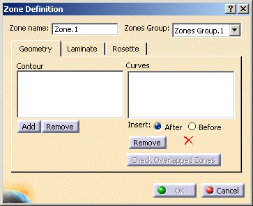
A name is proposed by default for the zone that you can modify.
In our example, we changed the name to Z1-1. -
Select the Zones Group to contain the zone.
-
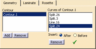
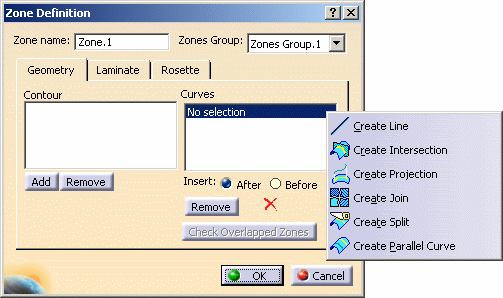
The Geometry tab lets you define a contour in the zone.
-
The Laminate tab lets you define the number of layers per association material / direction (thickness).
Select the Material from the drop-down list.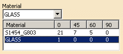

The elements in the list were initialized when defining the materials in the Composites Parameters dialog box. -
For each material, define the number of layers with a direction of 0, 45, etc.
-
The Rosette tab lets you define the axis (X, Y, Z) in which the directions are referenced.
Select the axis.

-
Click OK in the Zone Definition dialog box to create the zone.
The feature is added to the specification tree, under the Zones Groups.xxx node.
You can click Check Overlapped Zones to check that the zone contour does not overlap with another zone contour. -
Perform this scenario as many times as you need to create zones.
In our example, we created five zones in Zones Group.1, each zone containing one contour; and two zones in Zone Groups.2, the first zone containing one contour, and the second zone containing two contours.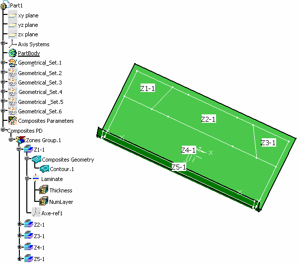
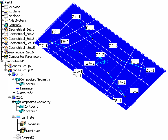
Two knowledge parameters are stored under the zone, in the Laminate node. They enable you to customize the geometry used to create the zones and tapers and the associability of the zones laminate.
Selecting a Curve Twice to Create the Zone Contour
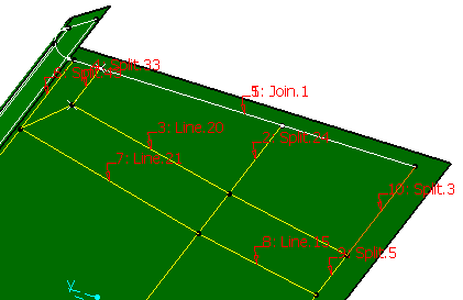
For instance, to obtain the zone contour displayed in the example below, the same curve has been selected twice.
 |
-
Create a single curve in your part by selecting three splits and using the join functionality.
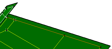
-
Click the Zones icon
 .
. -
Select the curves to define the zone contour as shown above.
To obtain a closed contour, you have to select twice Join.1 as the first and the fifth curve.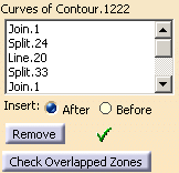
-
Select the Laminate you need.
-
Click OK to create the zone.
![]()
