Defining a Plies Group

This task shows you how to define a plies group that contains the plies you will further create.
A ply is a piece of fabric made of several contours and set of zones.
Available in Composites Engineering Design (CPE)  and Composites Design for Manufacturing (CPM).
Open the PliesGroup1.CATPart document.

 
  1. Click Plies Group .
    The Plies group Definition dialog box is displayed.
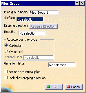
    A name is proposed by default for the plies group that you can modify.

  2. Select the surface on which the plies will be created.
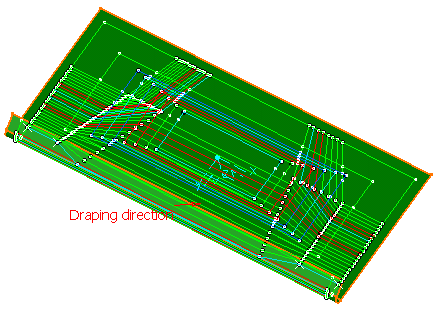
    The draping direction is displayed in the 3D geometry.
    You can click Reverse Direction to invert its direction.
    Here is an example for the first zone group.
  1. Decide whether you want to impose the same draping direction to all the plies that the plies group will contain or not. To do so, select or clear the Lock plies draping direction check box.

    If you select the Lock plies draping direction check box:
    • all the plies of the plies group will inherit the draping direction defined in the plies group,
    • in the Ply definition dialog box, the Draping direction capability will be disabled, the Reverse Direction button will be inactive and the inverting the draping direction by clicking its arrow will not be possible.
    • if you decide to lock the draping direction after having already created plies, a message will be displayed warning you that some plies have a different draping direction:
      • if you click OK to continue, the draping direction of those plies will be inverted to match the draping direction of the plies group.
      • if you click Cancel, the Lock plies draping direction check box in the Plies group definition dialog box is cleared and the draping direction of those plies remains unchanged.
    • if you import a stack-up file:
      • if all the plies have the same draping direction as the plies group, nothing changes regarding the draping direction,
      • if all the plies have the same draping direction, but different from that of the plies group, the plies group will take that draping direction,
      • if some plies have a different direction, a warning is displayed, giving you the possibility of:
        • clearing the Lock plies draping direction check box,
        • or make the plies inhering the draping direction of the plies group,
        • or cancel the import.

    If you do not select the Lock plies draping direction check box:

    • you will be able to change the draping direction of plies irrespective of that defined for the plies group,
    • the draping directions of the ply table will be applied to the plies irrespective of that defined for the plies group.
 
  1. If necessary, select the type of rosette transfer to be applied in Producibility, Producibility Inspection or Fiber Direction:

    • Cartesian: this rosette transfer type is suitable for panels with a low curvature.
    • Cylindrical: this rosette transfer type is suitable for parts with a high curvature.
      This mode requires that you select a Neutral Fiber, i.e. the axis of the cylindrical shape to be used. The X-axis of the rosette will correspond to this neutral fiber.
  2. Select the For non structural plies check box to indicate that plies in this plies group are non structural.

  3. Click OK to create the plies group.
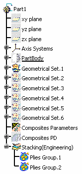
    The feature (identified as Plies Group.xxx) is added to the specification tree, under the Stacking node.
    This node will contain the structure for all the defined zones.

  4. Perform this scenario as many times as you need to create plies groups.
    In our example, we created two plies groups.
 

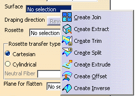
Should you need to create the surface or the rosette, right-click in the appropriate field and create the element you need.

Refer to Generative Shape Design & Optimizer User's Guide for more information.

If you need to hide or display a Plies Group, right click in the specification tree on Plies Group.xxx and select Hide/Show 3D contour.