|
The Offset
command is used to redefine the behavior of the
Reach Mode. The Reach Mode's
default behavior is to make the end point of the selected segment or skin
point reach the compass location. The Offset command allows
you to transfer that "end point" to another point
in the 3D space, which will then be used to perform inverse kinematics.
An example of this would be when the manikin must perform some inverse
kinematics while handling an object. In redefining the offset, the
compass may be also be snapped to manikin skin
points. Thus, the subsequent reach operation is resolved from the
skin rather than the central point of the segment.
There is the possibility to
create multiple offsets for the same segment and to decide which one
will be the active offset at the current time.
This is useful mainly in the manufacturing scenarios where the manikin is
taking care of multiple tools within a same simulation or workstation.
Each tool can then have its own offset specified on the manikin's hand. |
 |
- The Offset feature can be redefined for any segment or skin point
of any manikin
- The Offset feature is not available on the forearm model
- The name field will
allow modifying the name of the offset at creation and at edition.
- A list of those
offsets will be possible with one active offset at a time.
|
 |
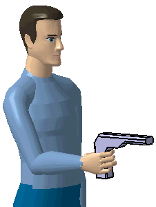
Redefining the offset to a point on a part
The goal of this task is to transfer the end effector of the manikin's
right hand to the tip of the tool the manikin is holding. This is done so
that when the Reach Mode is applied to the right hand, the
inverse kinematics will be transferred to the tip of the tool. The tool
will then do the reach on behalf of the hand segment. |
 |
-
From the main menu, select File > Open.
| The File Selection dialog box appears. |
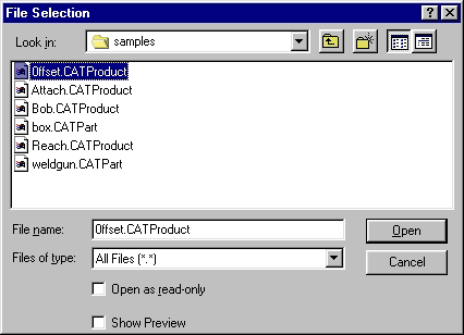 |
-
Select the
Offset.CATProduct file from the samples directory.
-
Use the Open button to open the file.
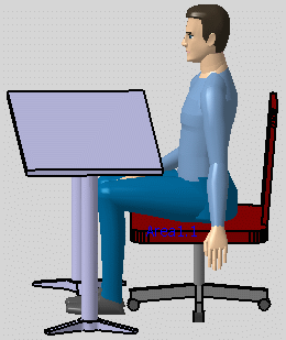
-
Position the manikin with respect to the geometry that
must be attached.
For this example, load the Attach catalog with the Load
Manikin Attributes from a Catalog
 and choose the Attach_sample posture.
 |
| This places the manikin posture so that it appears to be
handling the tool with its right hand. |
 |
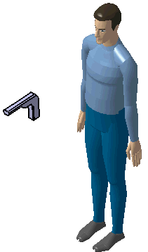
-
Select the Attach/Detach icon
 and attach the weld gun to the manikin's right hand.
-
Select the
Inserts a new Offset
 and select the manikins right hand.
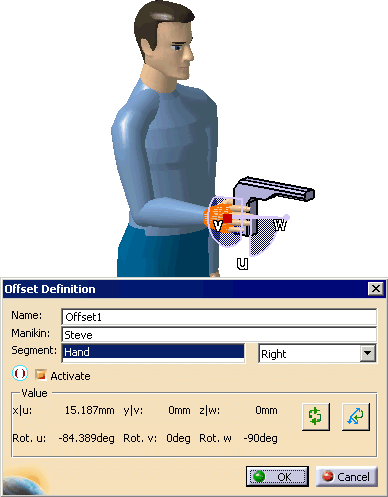
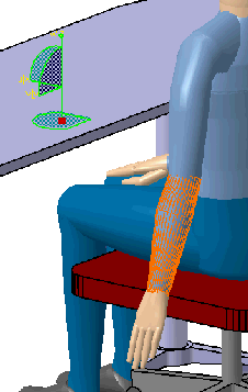
-
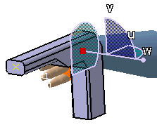
The Offset Definition dialog box is
displayed and the V5 compass automatically moves to the hand location.
-
Different elements of the Offset Definition dialog box
are described
-
The Name field is used to name the offset. The
system will assign an automatic name (i.e. Offset1, Offset2,...),
but you can override this name at your convenience.
-
The Manikin field indicates the name of the
manikin owning the offset. By selecting this field, you can
switch manikins, that is, transfer the offset to a different
manikin. The Segment field (and the Right/Left combo beside it)
indicates the current segment that owns the offset being
created/edited (in the snapshot above, the offset will be created
on the right hand segment). By selecting this field, you can
change the segment assignment of the offset, or transfer the
offset to another segment.
-
The Activate checkbox allows you to toggle the
activation and deactivation of the offset. In the snapshot above,
the offset is currently active.
-
The Value frame displays the current location of
the offset, in terms or translation (first row) and rotation
(second row). This frame also incorporates a Reset button,
which repositions the offset back to the origin of the segment,
and a Reverse Compass button which reverses the Z direction of
the compass.
-
The Cancel button cancels the creation/edition
operation.
|
-
Place the compass at the tip of the tool. This is the
desired location for the inverse kinematics.
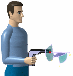
-
Select the OK button.
-
The offset is now transferred from the hand to the tip
of the tool (green X).
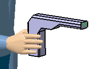
-
Following these procedures, create a offset on the side
of the gun as shown.
-
In the PPR tree, the two offsets are shown.
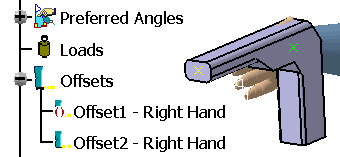
-
Notice that Offset1 is deactivated, and Offset2 is
activated.
-
To deactivate Offset2, right-click on Offset2 for the
contextual menu, and select Deactivate.
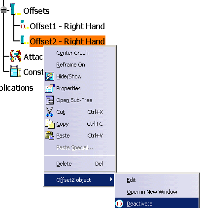
-
This could also would Activate a Offset that is
Deactivated.
|
|
Redefining the offset to a point on the
skin
|
| |
-
From the samples directory, open the
OffsetSkin.CATProduct file.
-
Select the desired segment: for this example, the
forearm and the Offsets node.
-
Follow the procedures for
Insert a new Offset.
-
Using the red handle, drag the compass to the desired
point on the skin surface of the forearm.
-
In the dialog box, select OK.
-
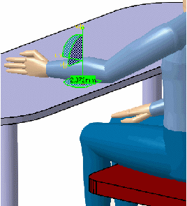
From the Manikin Posture toolbar, select the Reach
(position only).

-
Using the red handle, move the compass to the top
surface of the table.
-
Select the manikin's forearm.
| The forearm's offset point reaches the compass point on the
table. |
 |
|
|
|
When editing the offset of any segment, the compass is
automatically placed at the current offset location. The default offset
location is the end point of the segment being edited. |
| |
To reset the offset back to its default value, open the
Offset dialog box on the segment and click the Reset button. Select
Close to close the dialog box. |
| |
The Reverse Direction button reverses the
current orientation of the compass. This feature is typically used when
the geometry is manipulated in design mode where the compass goes inside
the geometry when snapped to an object. |