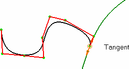
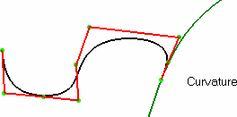
These curves can be created in space or lie on a geometrical element, or both. When the curve lie on a geometrical element and the later is modified, the curve is updated automatically, provided you choose the Automatic update option in Tools > Options > Mechanical Design > Assembly Design > General tab.
Open a new CATPart document.
-
Click the 3D Curve icon
 .
.
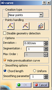
The 3D curve dialog box is displayed. -
Choose the curve creation type.
- Through points: the resulting curve is a multi-arc curve passing through each selected point.
-
Control points: the points you click are the control points of the resulting curve
- Near points: the resulting curve is a single-arc, with a set degree and smoothed through the selected points.
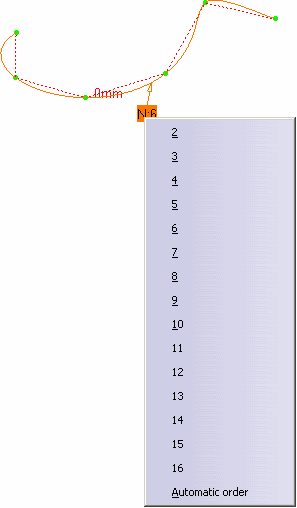
You can edit the order by right-clicking the displayed text (displayed using the U, V Orders icon
from the FreeStyle Dashboard or the Order option from Tools > Options, Shape > FreeStyle > General tab), and choosing a new order value.
The computed value is displayed near the Auto tag.
- The Deviation option enables the user to set the maximum deviation between the curve and the construction points.
The result is a set degree through the selected points.
- The Segmentation option enables the user to set the
maximum number of arc limits. These arcs are made of points and are
inserted into the curve automatically.
The minimum value is set to 1.
- The Max Order option enables you
to set a bound for the computation of a mono-arc curve.
This option is only available with the Control Points and the Near Points types (provided the Automatic Order is selected).- Control Points: when the Max order value is exceeded, the mono-arc curve becomes a multi-arc curve. As a consequence, the Max order value is no longer taken into account, as arcs have always 6 as order.
- Near Points: you cannot create a 3D curve with an order higher than
the Max order value. The Max order value is always taken into account,
whatever the result (mono-arc or multi-arcs curve).
The maximum value for the Max order is the same as defined in Tools > Options > Shape > FreeStyle. If you decrease the value in Tools > Options and it is lower than the Max order value, then the latter value prevails.
- Smoothing options are available to parameterize the curve:
- Chord Length (default parameterization)
Smoothing parameter = 0
- Uniform
Smoothing parameter = 0
- Smoothing parameter: enable a better control points distribution of the smoothed curve.


Smoothing parameter = 50
Smoothing parameter = 130
-
Move the pointer over a point.
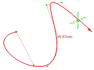
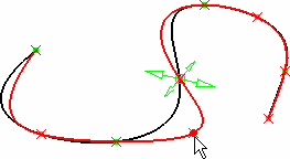
A manipulator is displayed allowing you to modify point location as you create the curve.
By default, this manipulator is on the last created point.A contextual menu proposes several options to construct the 3D curve.
-
Click the Insert a point icon
 within the
dialog box.
The curve freezes. -
Click the segment, between two existing points where you wish to add a new point and click the point location.
Once the point has been created, you are back to the edition capabilities on the curve.
-
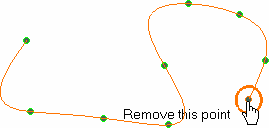
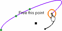
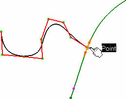
If the point is a point in space (free), move the pointer close to the point or a wire to which it should be linked. You can then move the pointer over a geometric element and:
-
move the point to the indicated point by clicking
-
press and hold the Control key (Ctrl) to project this point onto this element according to the shortest distance from the point initial location.
-
-
If the point was lying on another point or a wire (curve, line, spline, etc.), it is freed from its constraint onto this element, and can be moved to any new location in space.
-
Click OK to create the curve.
A 3DCurve.xxx appears in the specification tree.
-
Check the Disable geometry detection button, when you need to create a point close to a geometric element yet without constraining it onto the existing geometry.
- Check the Hide previsualisation curve to hide the previsualisation curve you are creating.
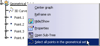
Selecting all 3D points
It is possible to select all the points either in the specification tree or directly in the geometry.
The Select all points contextual menu is available within the 3D curve action only, when the 3D Curve dialog box is open.
- In the specification tree:
- select the geometrical set just by clicking it, or
- right-click the geometrical set and choose Select all points in the geometrical set from the contextual menu, or
- select a point in the geometrical set, right-click it and choose Select all points in the geometrical set from the contextual menu.
- In the geometry: select a point, right-click it and choose Select all points in the geometrical set from the contextual menu.
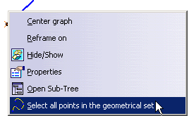
Contextual Options
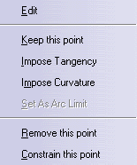
Double-click your curve, right-click on the manipulator to display the contextual menu.
| Through Points | Control Points | Near points | |
| Edit | X | X | X |
| Keep this point | X | X | X |
| Impose Tangency | X | X | |
| Impose Curvature | X | X | |
| Set as Arc Limit | X | ||
| Remove this point | X | X | X |
| Constrain this point | X | X | X |
Editing
-
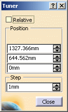
Right-click any of the manipulators, and choose the Edit contextual menu to display the Tuner dialog box. This option allows you to redefine the tangency position (X, Y, and Z axes), and its vector's step.
The Reset Origin button allows you to reset the origin of the relative position.
Keeping a point
-
Right-click an existing point and choose the Keep this point menu item to create a point at this location.
A datum Point.xxx appears in the specification tree.
You can create a Point.xxx either on each control point or on the selected control points.
Imposing a Tangency Constraint
Automatic Constraint
- When a curve is created in Through points or Near
points mode, and its first point is constrained on any point of
another curve, the new curve automatically is tangent to the curve on
which its first point is constrained. As soon as the curve's second point
is created, the imposed tangent is displayed on the new curve.
To deactivate the default option, uncheck the Impose Tangency contextual menu on the tangent vector.
Tangency Constraint on Points
Depending on the creation mode, you can impose this constraints on a limited number of points:
- In Through points mode: tangency can be imposed on any point
- In Near points mode: tangency can be imposed independently on each end points only
- In Control points mode: no tangency constraint can be imposed (end points can be constrained on other elements as described in step 7 above. See also Constraining a Control Points Curve.
Here is how to do it:
Open the FreeStyle_03.CATPart document.
-
Move the pointer over an existing point, double-click it.
The 3D curve dialog box appears.
-
Right-click and choose the Impose Tangency menu item.
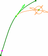
- two arrows representing the normed directions (vectors) of the tangency
- circles representing manipulators for this vector
- pulling the arrow
- gliding the circles
- double-clicking the arrow to invert the tangency direction
You can set the tangency length by clicking on the arrow then dragging the mouse.
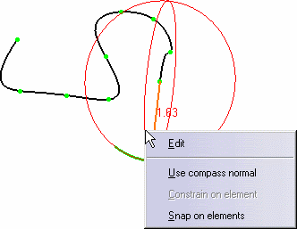
- Use current plane orientation (P1)/Use compass normal
(P2): the tangency constraint is defined in relation to the normal to the
current plane, possibly defined by the normal to the compass main plane
When several points are constrained on the compass, all are modified if the compass settings are changed.
When this option is checked, the direction cannot be modified directly using the vector manipulator, but only using the compass.
- Constrain on element: available only when a point is
already constrained on a curve. The curve being created/modified becomes
constraint in tangency or curvature to the constraining curve at this
point.
- Tangency constraint: in this case you can only modify the vector's norm using the Edit contextual menu, and no longer the vector's direction, the latter being defined by the constraining curve.
- Curvature constraint: in this case you neither modify the vector's norm using the Edit contextual menu, nor the vector's direction, the latter being defined by the constraining curve.
By default, when the tangency vector is constrained onto another curve, its initial direction is retained.
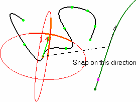
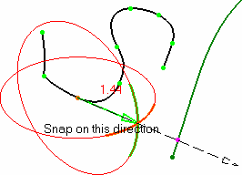
- Snap on elements: the vector's direction is defined by an external element. Grabbing a manipulator, you drag the pointer over a curve, and the curve becomes tangent to the curve detected by the pointer.
If the pointer is over a point the direction is computed as the line going from the constrained point and the detected point.
If the pointer is over a plane, the tangency is defined by the normal to this plane.
- When snapping on an element, use the Control (Ctrl) key to obtain an exact snap, taking into account both the detected element and the vector's norm.
- Use the Shift key as a shortcut to activate/de-activate the Snap on elements option when passing the pointer over geometric elements.
Control Points Curve Constraint
Right-click the text to display the contextual menu from which you can choose another continuity type: tangency, or curvature.
- in Point continuity, only the selected point is constrained
- in Tangent continuity, the selected point and the next one are constrained
- in Curvature continuity, the selected point and the next two points are constrained
This means that these second and third points will be modified if you move the constrained point along the constraining element, using the manipulators. However, you cannot constrain these points, because they are considered as already constrained. If you try to do so, a warning message is displayed. Nevertheless, you can add/remove points directly after the constrained end point, and the system resets the points as second and third points to be affected by the constraint, where applicable.
A Continuity warning is displayed when trying to move the manipulators in a direction that is not compatible with the set constraint.
Imposing a Curvature Constraint
Right-click an existing point and choose the Impose Curvature menu item. An arrow representing the curvature direction (vector) is displayed. Modifying the vector direction modifies the curvature direction.
The direction of the curvature is constrained in the plane defined as normal to the tangent vector.
- To impose a curvature continuity, you must ensure that a tangency continuity already exists.
- This option is only available for the Through points and Near Points creation type.
Setting as Arc Limit
Right-click an existing point and choose the Set As Arc Limit menu item to start/stop an arc limit on this point. The curve will pass through this point.
-
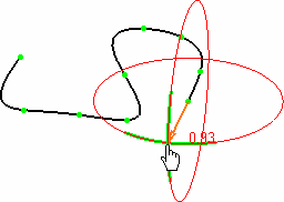
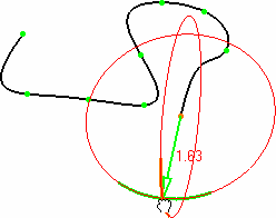
Use the F5 key to move the manipulators into a different plane of the compass. See Managing the Compass.
-
Use the standard shortcuts (Ctrl and Shift keys) to select, multi-select, and unselect any combination of control points on these curves.
-
You cannot add a point past the end points. To do this, you need to add a point before the end point, move the new point where the end point lies, then move the end point to a new location.
-
The creation plane for each free point is defined according to the current plane/compass orientation on the previous point. Therefore you can change creation planes within the same curve, by setting a new current plane/compass orientation on several points.
