-
Select Tools > Utility...
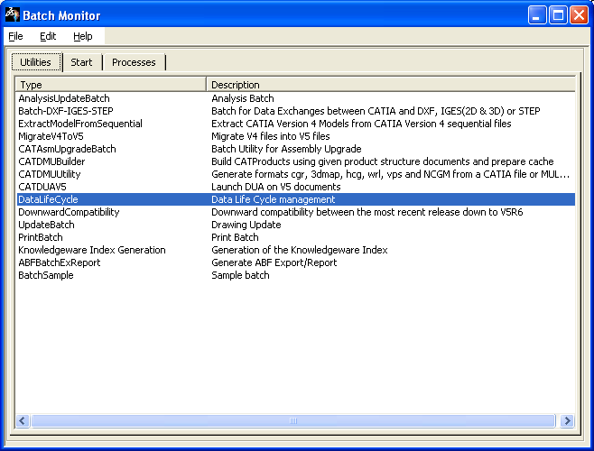
The Batch Monitor window opens. -
Double-click the DataLifeCycle utility:
The DataLifeCycle dialog box opens. Set the migration batch environment and select the document to migrate. 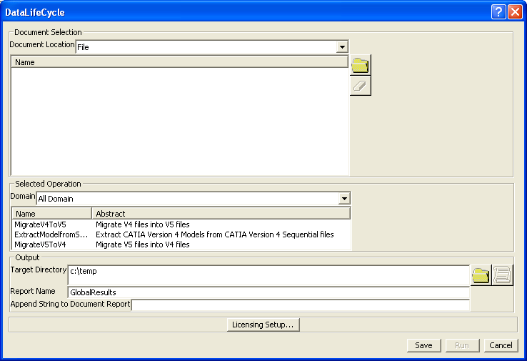
-
Click Run. When the migration is performed, you get the migration.CATProduct in your target directory, as well as CATParts and other documents.
-
Open the migration.CATProduct in CATIA V5.
If the Update All icon is activated, you need to update your document.
-
If need be, click Update All
 .
.You may have a message indicating a problem in the geometry area such as: - A twisted configuration on a bundle segment
See Reference Information. - A fillet which needs to be modified
Refer to Part Design User's Guide.
- A twisted configuration on a bundle segment
-
Then you need to complete the information for a certain number of V5 components.
Select the reference so the modification will be performed on all the instances.-
For single insert connectors
On V5 single insert connectors, the Representation of the connector connection point and the Contact constraint correspond to the migrated point of the CPP of the V4 SIC.
Coincidence and Orientation constraints must be added, using Electrical Library.
- Select the single insert connector as shown above:
GLY-002
See the specification tree below. - Using the right-mouse button, select Open in New
Window to open the CATPart reference.
- Double-click the *CPP4 in the Electrical
container
 .
.The Connector Connection Point Definition dialog box opens: 
Refer to Electrical Library User's Guide - User Tasks - Defining Electrical Connection Points. - Select the face as Contact
- Select the axis as Coincidence
The result looks like this: 
- To use the Orientation constraint on this sample, you would need to create the geometry (such as a notch). Refer to Generative Shape Design User's Guide.
- Click OK to validate the entry made.
The publication has been generated. 
Specification Tree
Repeat these steps for the other single insert connector: 
- Select ELEC2
See the specification tree below. - Add the placement constraints to the *CPP5.
- Using Electrical Library:
Disconnect  then re-connect
 the single insert connectors to create the mechanical
constraints.
the single insert connectors to create the mechanical
constraints.
Refer to Electrical Library User's Guide - User Tasks - Connecting/Disconnecting Devices.
Specification Tree
- Select the single insert connector as shown above:
GLY-002
-
To connect a single insert connector to an equipment or connector shell
You need to add a cavity connection point to the single insert connector and add or complete the definition of a cavity to the equipment or connector shell. - Adding a cavity connection point to the single insert
connector
- With the same methodology, select migration_ECP-GLY-001_xxSET2 for example and open it in new window.
- Using Electrical Library, click Define
Cavity Connection Point
 .
.Select the face for the Representation and the Contact, and the axis for the Coincidence. 
Refer to Electrical Library User's Guide - User Tasks - Defining Electrical Connection Points.
The cavity connection point is created:
- Completing the definition of a cavity to the equipment or
connector shell: here a connector
shell.
- Select the connector shell: SHELL-GLY-002
and open it in new window.
The cavities exist, but information is missing: you need to define the geometry of a pocket for example. Refer to Part Design User's Guide.
- Then using Electrical Library, select GLY-01 and
click Define Cavity
 .
.Select the pocket for the Representation, the face for the Contact, and the axis for the Coincidence.
Repeat the operations for GLY-02.
Refer to Electrical Library User's Guide - User Tasks - Defining Electrical Connection Points.
The cavity definition is completed:
- You now need to connect the single insert connector
to the connector shell:
Click Connect Electrical Devices Select the single insert connector 
then the connector shell cavity. 
- Select the connector shell: SHELL-GLY-002
and open it in new window.
- Adding a cavity connection point to the single insert
connector
-
For information about other elements to be added to complete the electrical data in V5, refer to About Device Migration.
Also refer to Electrical Library User's Guide.
-