To perform the migration of the electrical data (geometry and technology), you first need to set up options for the:
These options can also be defined using:
- Tools > Options... > General > Compatibility > Migration Batch tab
- Tools > Options... > General > Compatibility > Electrical tab
- and Tools > Options > General > Compatibility > V4/V5 Space.
Refer to the Infrastructure User's Guide (Customizing Settings - General - Compatibility category).
![]()
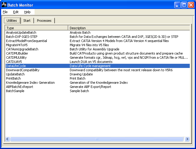
To do so, you need to access to the Batch Monitor:
-
Select Tools > Utility...
The Batch Monitor window opens. -
Double-click the DataLifeCycle utility:
The DataLifeCycle dialog box opens. 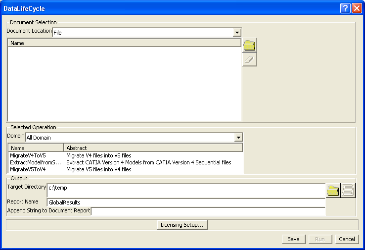
Setting up the Electrical Migration Batch
-
Click MigrateV4ToV5
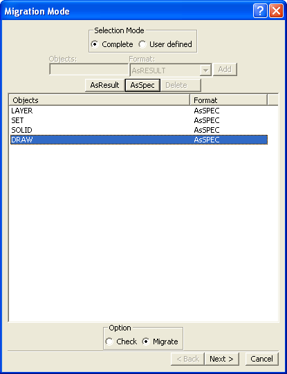
Insure that all objects are set to 'AsSpec'as the migration as the migration is not supported by V4 electrical elements.
-
Click on Next, the following dialog box opens

-
Check Set and Ditto in Structural Elements, else some Electrical Elements won't be migrated. Insure that the Migration Interface is set to CATIE3DMigration, then click Finish.
Setting up the Geometrical Bundle Migration Mode
-
Still in the Interactive Options dialog box, select the Electrical tab.
This tab lets you define whether or not you want:
-
Each GBN migrated as a product in a separate CATProduct:
in this case, select Product.
 By default, Product is selected.
-
Each GBN migrated as a component under the root product:
in this case, select Component.

Choosing the right migration mode option is important since it determines how geometrical bundles will be stored in ENOVIA LCA: - Migrating them as products lets you store them in ENOVIA LCA using Workpackage mode
- Migrating them as components lets you store them in ENOVIA LCA using Explode mode.
-
-
Select the option of interest.
Setting up the Bundle Segment Migration Mode
-
Still in the Electrical tab.
This tab lets you define whether or not you want:
-
Each V4 BNS of the GBN migrated to a separate CATPart:
in this case, select Bundle segments.
-
All the V4 BNSs of the GBN migrated to a single CATPart:
in this case, select Multi-branchable document. Multi-branchable document is the default value.
It is recommended to use this option as it reduces the number of CATPart documents generated during the migration.
-
-
Select the option of interest.
Setting up Isolated Mock-Up Solids migration
-
Still in the Interactive Options dialog box, select the V4/V5 SPACE tab.
This tab lets you define an option for the Isolated Mock-up Solids migration:
Isolated Mock-Up Solids (SolidM) means that they have no history nor specifications stored.
For the migration two options are available:
-
as CGR: the SolidM conversion as CGR means that you will only get the meshing view (visualization mode).
as CGR is the default value. -
as PartBody: the SolidM conversion as PartBody means that you will be able to see the geometry of the solid to edit it.
Refer to V4/V5 SPACE tab in Infrastructure User's Guide.
(Customizing Settings - General - Compatibility category). -
-
Select as PartBody in the context of the electrical migration to be able to add technology.
-
Once you have selected your options, click OK to validate.
You are back in the MigrateV4ToV5 dialog box. -
Select a target directory (where the V5 documents will be created).
-
Select the V4 documents to be converted.
You are ready to migrate your V4 electrical data.
 |
Select the files to migrate and the path for the result as explained in the utility documentation and run the batch.