You will also learn how to:
You can also copy an existing geometric tolerance. You can set text properties either before or after you create the text.
-
Click Geometrical Tolerance
 in the Dimensioning toolbar (Tolerancing
sub-toolbar).
in the Dimensioning toolbar (Tolerancing
sub-toolbar). -
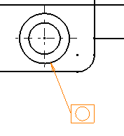
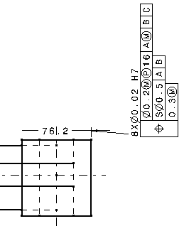
Select an element (geometry, dimension, dimension value, text or point) or click in the free space to position the anchor point of the geometrical tolerance.
-
If you select an element, the anchor point will be an arrow. Note that you can modify this symbol by editing the annotation leader.
-
If you select a point in the free space, the anchor point will be a small balloon.
")
-
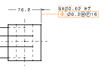
If you select a dimension, the anchor point will be at the intersection of the dimension line and the extension line.

-
If you press the Shift key and select the extension line, the leader is perpendicular to the extension line and the anchor point corresponds to the position of the cursor when you click to create the geometrical tolerance.
-
If you select a dimension value or a text, no leader will be created. The geometric tolerance will be displayed just below and parallel to the element you selected.
")
-
-
Move the cursor to position the geometrical tolerance and then click at the chosen location. The Geometrical Tolerance dialog box appears.

- At this step, you can apply the parameter values of an existing geometric tolerance to the tolerance you are creating: to do this, simply select the existing geometric tolerance.
- If you have selected the Use style values to create new
objects check box in Tools > Options > Mechanical Design
> Drafting > Administration tab, the Geometrical
Tolerance dialog box is pre-filled with custom style values
(as defined in the Standards Editor). In this case, Properties
toolbars and the Tools Palette are disabled during the
creation of the geometrical tolerance.
On the other hand, if you have not selected this option, the Geometrical Tolerance dialog box is pre-filled with the last entered values (if any). In this case, Properties toolbars and the Tools Palette are active during the creation of the geometrical tolerance. - You can reset the current style values in the Geometrical Tolerance dialog box at any time using the Reset button.
-
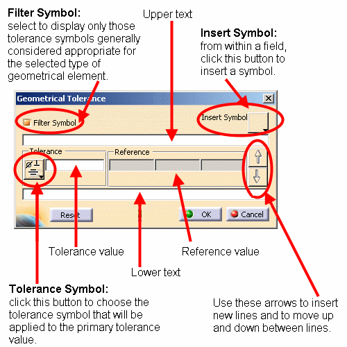
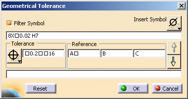
Select the Filter Symbol check box to filter the available tolerance symbols according to the type of geometrical element you selected (if any).
If you did not select any geometrical element, the tolerance symbols will not filtered. -
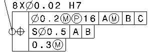
Specify the tolerance type by clicking the Tolerance Symbol button and selecting the appropriate symbol.
-
Type the tolerance value in the Tolerance value field, adding symbols as needed. To do this, position the cursor at the proper location in the field, and click the Insert Symbol button to choose the appropriate symbol.
You can add symbols to the tolerance and reference value as well as to the upper and lower text. -
Type the reference values in the Reference value fields, adding symbols as needed.
-
To add a new geometrical tolerance, click the Next line arrow button and repeat steps 4 to 5.
-
Type the upper and lower texts in the appropriate fields. You may also add symbols if you want to.
The geometric tolerance is updated as you define values for each field.
-
Click OK when you're done. The geometrical tolerance is created.

-
You can add an all-around symbol to the leader. To do this, select the geometrical tolerance, right-click the yellow manipulator on the arrow and select All Around from the contextual menu.
Specifying Leader Orientation
You can orient the geometrical tolerance leader perpendicularly to the element to which it is associated (for example, if the leader is associated to a dimension, you can position the leader parallel to the dimension line and orthogonal to the extension line).
For this, you have two different possibilities:
- Either go to Tools > Options > Mechanical Design > Drafting > Annotation and Dress-up tab and check Snap by default (SHIFT toggles). Then, click the Configure snapping button and select either On orientation or Both. To orient directly the geometrical tolerance leader perpendicularly to the associated element, press the Shift key before clicking in the drawing to position the tolerance (see previous scenario, step 3).
- Or go to Tools > Options > Mechanical Design > Drafting > Annotation and Dress-up tab and check Geometrical tolerance in Annotation Creation. The leader will be oriented perpendicularly to the geometry by default. In this case, pressing the Shift key will let you orient it differently.
Specifying Geometrical Tolerance Orientation
To make the tolerance vertical, hold the ctrl key before clicking in the drawing to position the tolerance (previous scenario, step 3).
 |
![]()