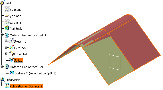
That is why ordered geometrical sets introduced notions of succession of steps that define the design, and absorption.
Creation features create a new object and modification features create a new state in an existing object as well as absorb the preceding state(s). Absorbed features are neither visible nor accessible, as if ''masked'' by their absorbing feature.
In an ordered geometrical set, the order of apparition of features in the specification tree is consistent with the steps of creation of the design.
Unlike features within a geometrical set, features in an ordered geometrical set can be set as current: a given step of the design creation is chosen and what is located after it is neither accessible nor visible.
- inserting an ordered geometrical set
- defining an in work object
- visualizing features within an ordered geometrical set
- selecting features within an ordered geometrical set
- removing an ordered geometrical set
- removing a feature within an ordered geometrical set
- sorting the contents of an ordered geometrical set
- reordering components within an ordered geometrical set
- reordering features
- modifying children
- replacing features
- switching from ordered geometrical set to geometrical set
- inserting and deleting inside and ordered geometrical set
- editing features within an ordered geometrical set
You will find other useful information in the Managing Groups and Hiding/Showing chapters.
To do this, while in the Generative Shape Design workbench:
- Choose Tools > External View... from the menu bar.
The External View dialog box is displayed. - Select the element belonging to an ordered geometrical set that should always been seen as the current element when working with an external application.
- Click OK in the dialog box.
The selected element will be the visible element in other applications, even if other elements are created later in the .CATPart document, chronologically speaking. To check whether an external view element has already been specified, choose the Tools > External View... menu item again. The dialog box will display the name of the currently selected element. This also allows you to change elements through the selection of another element. Note that you cannot deselect an external view element and that only one element can be selected at the same time.
You can also open the OrderedGeometricalSets1.CATPart document.
Inserting an Ordered Geometrical Set
-
In the specification tree, select an element as the location of the new ordered geometrical set.
This element will be considered as a child of the new ordered geometrical set.
Inserting an Ordered Geometrical Set does not break the succession of steps as the order applies to all the elements of a same root ordered geometrical set. -
Select Insert > Ordered Geometrical Set... from the menu bar.

The Insert ordered geometrical set dialog box is displayed. The Features list displays the elements to be contained in the new ordered geometrical set. 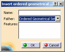
-
Enter the name of the new ordered geometrical set you wish to insert.
-
Use the Father drop-down list to choose the body where the new ordered geometrical set is to be inserted. All destinations present in the document are listed allowing you to select one to be the father without scanning the specification tree. They can be:
-
ordered geometrical sets
-
parts
By default the destination is the father of the current object. By default the ordered geometrical set is created after the current feature. -
-
Select additional entities that are to be included in the new ordered geometrical set.

If all selected entities belong to the same ordered geometrical set, the father of the new ordered geometrical set is automatically set to the father of these entities. -
Click OK to create the ordered geometrical set at the desired location.
The result is immediate. CATIA displays this new Ordered Geometrical Set.x, incrementing its name in relation to the pre-existing bodies, in the specification tree. It is created after the last current ordered geometrical set and is underlined, indicating that it is the active ordered geometrical set.
You can insert an ordered geometrical set after the current feature.
You cannot create an ordered geometrical set within a geometrical set and vice versa.
You can insert a body into an ordered geometrical set.
For further information, refer to the Inserting a Body into an Ordered Geometrical Set chapter.
Defining an In Work Object
If the new feature to be inserted is a modification feature, features after the In Work object may be rerouted to the new created feature.
Visualizing features in an Ordered Geometrical Set
- Only features that come before the current object and that are not
absorbed by any feature preceding the current object are visualized in
the specification tree.
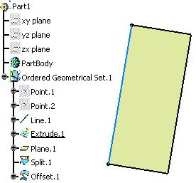
To do so, you can check the Geometry located after the current feature option in Tools > Options > Infrastructure > Part Infrastructure > Display tab. It allows you to also display the geometry located after the current feature.
- A color assigned to a feature is propagated to all the features that
successively modify this feature and so on.
This is why it is possible to set a specific color only on creation features.
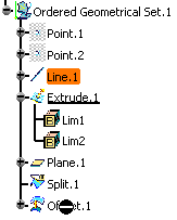
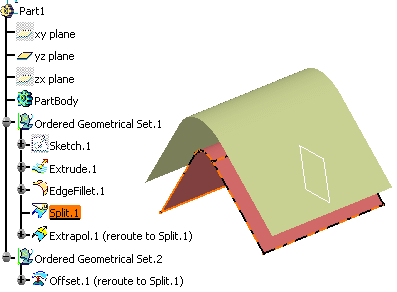
Therefore, changing the color of a modification feature modifies the color of the initial state.Here Extrude.1 is absorbed by Split.1. Therefore the color of Extrude.1 is propagated onto Split.1. 
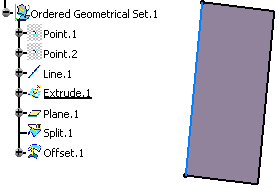

The same behavior applies on Show/No show attributes.
Selecting Features within an Ordered Geometrical Set
To ensure the consistency between the visualization in the 3D geometry and the selection in the specification tree, features that cannot be visualized in the 3D geometry cannot also be selected in the specification tree.
Removing an Ordered Geometrical Set
-
Right-click the ordered geometrical set then select the Delete contextual command.
The ordered geometrical set and all its contents are deleted.
Removing a Feature within an Ordered Geometrical Set
-
Right-click the feature then select the Delete contextual command.
- Deletion of a modification feature: the system reroutes the children
on the element that is modified. Therefore the deleted feature will be
replaced by the modified feature of upper level.
In our scenario, Split.1 is deleted. As a consequence, Offset.1 now points Extrude.1.
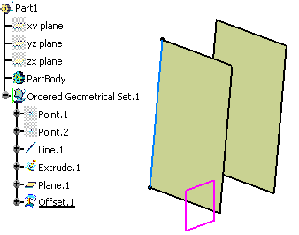
-
Deletion of a creation feature: no reroute is possible.
Sorting the Contents of an Ordered Geometrical Set
-
Right-click the Ordered Geometrical Set.1 from the specification and choose the Ordered Geometrical Set.1 object > AutoSort command.
Instantly, the contents of the Ordered Geometrical Set are reorganized to show the logical creation process.
The geometry remains unchanged. Datum features are put first in the specification tree.
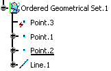
Reordering Components within an Ordered Geometrical Set
Reordering a creation feature based upon a modification feature
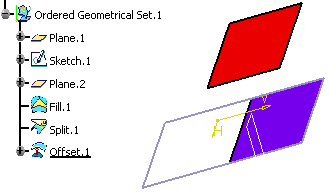
The Ordered Geometrical Set contains Split.1 (in purple) that splits Fill.1 by a white vertical plane, and Offset.1 (in red) is an offset of Split.1.
-
Right-click the Ordered Geometrical Set.1 from the specification tree and choose the Ordered Geometrical Set.1 object > Reorder Children command.
The Reorder Children dialog box is displayed. 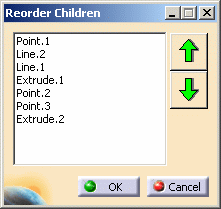
-
Select the element to be rerouted.
Here we chose to reorder Offset.1 (creation feature) before Split.1 (modification feature). -
Use the arrow to move Offset.1 up.

When the first element of the list is reordered upward, it becomes the last element. Similarly, when the last element of the list is reordered downward, it becomes the first element. -
Click OK.
Offset.1 is now located before Split.1 in the specification tree. If you define Split.1 as the In Work Object, you can see that Offset.1 is now based upon Fill.1.
Split.1 was not rerouted since Offset.1 does not modify Fill.1.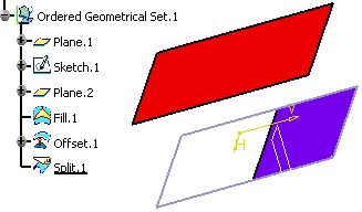
Reordering a modification feature based upon a modification feature
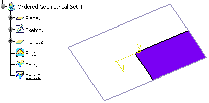
The Ordered Geometrical Set contains Split.2 (in blue) that splits Split.1 by a vertical plane. Split.1 itself splits Fill.1 (delimited by Sketch.1 in purple).
-
Right-click the Ordered Geometrical Set.1 from the specification tree and choose the Ordered Geometrical Set.1 object > Reorder Children command.
The Reorder Children dialog box is displayed. 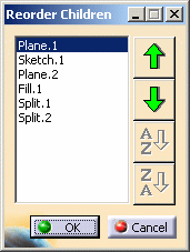
-
Select the element to be rerouted.
Here we chose to reorder Split.2 (modification feature) before Split.1 (modification feature). -
Use the arrow to move Split.2 up.
-
Click OK.
Split.2 is now located before Split.1 in the specification tree. Split.2 is rerouted onto the input feature modified by Split.1, which is Fill.1 (in blue).
Otherwise Split.2 would still split Split.1, which comes after Split.2 in the specification tree.
Indeed, when you edit Split.2, you can notice that the Split.2 was rerouted onto Fill.1... 
...and since Split.2 now modifies Fill.1, Split.1 was rerouted onto Split.2. 
An error message is issued if you try to move an element towards a position that breaks the order rules. Note that the feature defined as the In Work Object after the Reorder operation is not affected by this operation from an update point of view:
- when reordering upward, the feature located just before the new position of the reordered feature becomes the In Work object.
- when reordering downward, the feature just before the original position of the reordered feature becomes the In Work object.
You can use the Scan command after the Reorder operation to see what moved step by step.
Reordering Features
-
Generative Shape Design features
-
sketches
For further information, please refer to the Reordering Features chapter in the Part Design User's Guide.
Modifying Children
-
Right-click the sub-ordered geometrical set from the specification tree and choose the Ordered Geometrical Set.x object > Modifying children.
The Edit ordered geometrical set dialog box opens with the First element and Last element fields automatically valuated with the first and last elements of the ordered geometrical set. 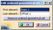
-
Select the elements you wish to place first and last.
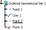
In our scenario, we chose Line.1 as the first element and Split.1 as the last element. 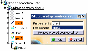
-
Click OK.
The specification tree is modified consequently.
Elements before or after the first and last elements are rerouted in the father ordered geometrical set.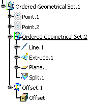
The Modify children command also allows you to remove the sub-ordered geometrical set. As a consequence, elements are rerouted in the father ordered geometrical set. 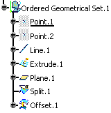
Replacing Features
As a consequence, the succession of steps of the ordered geometrical set is no longer respected. We advise you not to check this option but rather work in a geometrical set environment.
Switching from Ordered Geometrical Set to Geometrical Set
-
Right-click the Ordered Geometrical Set.1 from the specification tree and choose the Ordered Geometrical Set.1 object > Switch To Geometrical Set command.
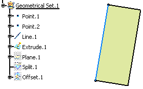
The Ordered Geometrical Set.1 becomes Geometrical Set.1, provided its name has been created automatically.
Absorbed features and features after the current object that were not visualized in the ordered geometrical set are put in no show in the geometrical set.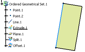

-
This command is only available on a root ordered geometrical set.
-
Switching from geometrical set to ordered geometrical set is not possible.
-
Colors may be modified.
-
Inserting and Deleting Inside an Ordered Geometrical Set
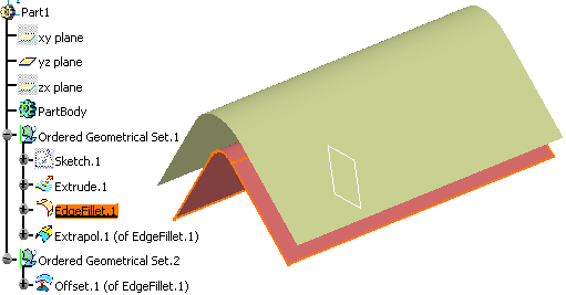
Using our example, had we selected the other side of Split.1, the replacement of the edge to extrapolate (defined in Extrapol.1 feature) would not have been possible.
The replace actions performed by the Delete command are generally the opposite of the replace actions performed by Insert command. Using our example, deleting Split.1 leads to the replacement of Split.1 by EdgeFillet.1. Nevertheless, bear in mind that deleting a feature can lead to a configuration different from the one preceding the insertion of a feature (for instance, if inserting a Trim feature, all inputs will be replaced by this feature but if deleting it, the Trim feature will be replaced by its main input).
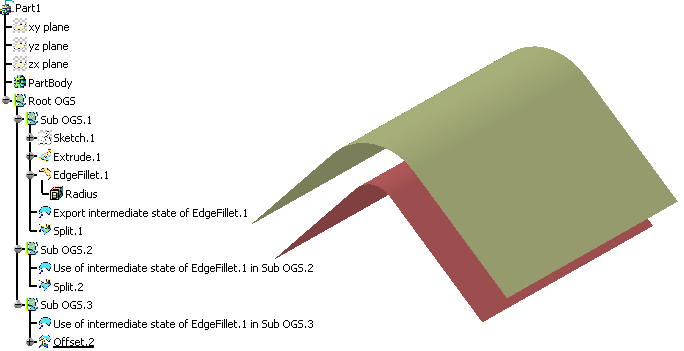
- multiple references to an intermediate state of design inside an ordered geometrical set,
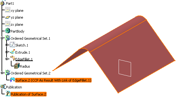
- external links to the "end design" specified inside an ordered geometrical set.
Multiple references
Using this construction, modifications applied to EdgeFillet.1 or to the copies of the copy will affect only the design in Sub OGS.1.
External Links
The external link has to reference Surface.2 or its publication.
Editing Feature within an Ordered Geometrical Set
If a feature is created as a creation or modification feature, then when editing it, you are prevented from changing the options that were used to define its type.
Command Name Panel options Blend Trim First Support, Trim Second Support Extrapol Assemble Result Shape Fillet - BiTangent Fillet Trim Support 1, Trim Support 2 Shape Fillet - TriTangent Fillet Trim Support 1, Trim Support 2 Edge fillet, Variable edge fillet, tritangent fillet, face-face fillet Trim Support Corner Trim element 1, Trim element 2 Circle-Bitangent and Radius Trim element 1, Trim element 2 Circle-Bitangent and Point Trim element 1, Trim element 2 Circle-Tritangent Trim element 1, Trim element 3 Connect Trim elements Sweep-Line (With Tangency Surface) Trim with tangency surface Sweep-Line (With Two Tangency Surfaces) Trim with first tangency surface, Trim with second tangency surface Sweep-Circle (One guide and tangency Surface) Trim with tangency surface Mating Flange Trim, Trim and Split Bead Base surface Relimitation Diabolo Base Element (Once selected, the reversal from plane to surface or vice versa is not allowed.
-
Click Corner
 .
.The Corner Definition dialog box opens. -
Choose the Corner On Support type from the combo list.
-
Deselect the Corner On Vertex option.
-
Select Line.1 as Element 1 and Line.2 as Element 2.
-
Check the Trim element 1 and Trim element 2 options to trim and assemble the two reference elements to the corner.
By selecting the Trim options, the corner is now considered as a modification feature.
-
Click OK to create the corner.
-
Double-click the corner (in the specification tree or in the 3D geometry) to edit it.
The Corner Definition dialog box opens. 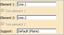
Both Trim options are disabled.
![]()

