This task shows how to scan the part and define a
current object without taking the complete part into account. Therefore, it
is useful for the analysis of the better understanding of the part design.
Both geometrical sets and ordered geometrical sets
can be scanned.
-
Select Edit > Scan or Define In Work Object... from the menu bar or click
 from
the Select toolbar.
from
the Select toolbar.The Scan toolbar appears enabling you to navigate through the structure of your part. Moreover, the part can be updated feature by feature. You actually need to click the buttons allowing you to move from one current feature to the other. Sketch elements are not taken into account by the command. 
-
Select the Scan mode to define the way of scanning:
Structure
The current position in the graph corresponds to the in work object.
Internal elements of sketches, part bodies and bodies, ordered geometrical sets, and elements belonging to a geometrical set are not taken into account by this mode.
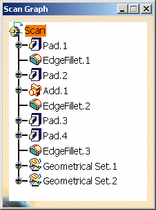
The Scan Graph dialog box appears and displays all the features belonging to Scan part.
Update
The current position in the scan graph does not correspond to the in work object: indeed the underlined object in the graph is not necessarily the one underlined in the specification tree.
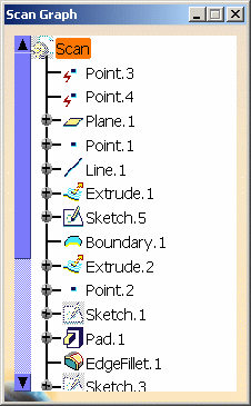
Datum features appear first; geometrical sets and ordered geometrical sets do not appear in the Scan Graph.
The part is put in no show, so is its 3D display, in order to build a new 3D display that contains the same features but in a different order.
As a consequence, if a geometrical set or an ordered geometrical set is in no show, it is ignored and its elements are considered as being in show.
To put the contents of this geometrical set or ordered geometrical set in no show, use the Geometrical_Set.x object > Hide components contextual command. Refer to the Hiding/Showing Geometrical Sets or Ordered Geometrical Sets and Their Contents chapter for further information.
-
Select a feature in the Scan Graph or in the specification tree. The application highlights the feature in question in the specification tree as well as in the geometry area and make it current.
In our example, we chose EdgeFillet.1. 
- A preview of the current object's parents is available:
- if the parents are visible: the thickness of lines and points is increased and the surfaces' edges are in dotted lines; faces and edges are highlighted.
- if the parents are not visible: the surfaces appear as transparent; lines and points are in yellow dotted lines.
- If a parent of the in work object is in no show, it is temporarily shown when its child is the in work object.
- A preview of the current object's parents is available:
-
Click Previous
 to move to the previous
feature, that is Pad.1.
 -
Click First
 to move to the first
feature, that is Plane.1 (the first feature after the two datum points).
In case there are several datum features, the application highlights the last one as there are all scanned at the same time. -
Click Next
 to move to
the next feature, that is Point.1.
Scanning Next and Previous skip datum and deactivated features. -
Click Last
 to move to the last feature,
that is EdgeFillet.3.
Moving to the next or last feature enables to update elements that are not up-to-date. -
Click First to Update
 to move to
the first element to be updated and consequently update it.
to move to
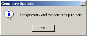
the first element to be updated and consequently update it.If both geometry and part are up-to-date, an information panel appears: 
-
Click this icon again to find the next element to be updated and so on until an information panel appears to inform you that both geometry and part are up-to-date.
-
Click Play Update
 to replay the
update of the geometry.
to replay the
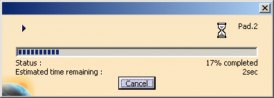
update of the geometry.A progression bar is displayed, while the scenario is being replayed. 
In case of update errors, the replay stops at the first error. The Update Error dialog box opens. -
Click Exit
 to exit the command.
In the geometry area and the specification tree, the application highlights the current object.
If the object was in no show, it is put in show as long as it stays current.
- Defining a feature as current without scanning the whole part is possible using the Define in Work Object contextual command on the desired feature. This feature is put in show if needed, and keeps its status even if another feature is defined as the in work object.
- When clicking a sub-element in the 3D geometry, it is in fact the feature used to generate this sub-element which is selected as the in work object. Likewise, this feature is edited when double-clicking a sub-element.
- When a collapsed contextual element is highlighted, it is the node of its set that is highlighted in the Scan Graph.
- To display 3D parameters attached to Part Design features, check the Parameters of features and constraints option in the Tools > Options > Infrastructure > Part Infrastructure > Display.
![]()

