Within this action, you can initialize the parting line with the Reflect Line
Then you modify and complete it by using the Spline
Several analysis tools can help you:
- Show mold area to display computed core, cavity and draft surfaces corresponding to a given pulling direction and draft angle.
- A highlight of the current created parting line.
The geometrical sets structure helps you organize this process.
Open the PartingLine.CATPart from the samples directory.
-
Click Parting Line
 in the Curves toolbar.
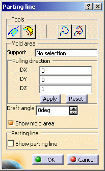
The dialog box is displayed:
-
Select the part as the Support you want to work on. The Support field is updated.
- If a main pulling direction has been defined, the Pulling direction frame is initialized with it.
- If no main pulling direction exists, the Pulling direction proposed by default is 0,0,1.
-
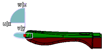
If the Show mold area check box is selected, the mold areas are displayed on the part (core in red, cavity in green, draft in blue).
-
You can modify the Pulling direction directly in the dialog box.
Click Apply to take your changes into account or Reset to revert to the initial values.
You can also modify the Pulling direction with the compass. In this case, you need not click Apply to take the changes into account. -
You can also modify the Draft angle dynamically.
-
Similarly, you can select the Show parting line check box to display the parting line.
-
Click
 to launch the
Reflect Line
command. It will give you a first outline of the parting line.
to launch the
Reflect Line
command. It will give you a first outline of the parting line.- Its dialog box is initialized with the current data.
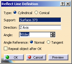
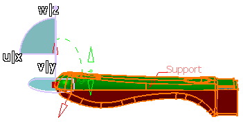
- Once you are satisfied, click OK in the Reflect Line Definition dialog box.
- Select keep all the sub-elements in the
Multi-Result Management dialog box.
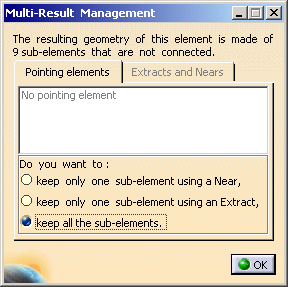
- The Reflect line is created.
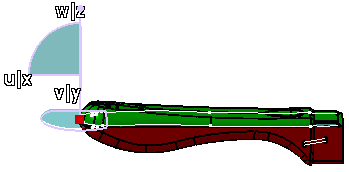
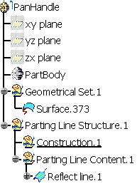
- Note that the Reflect line is created in a
Geometrical Set dedicated to the Parting Line in the
specification tree.
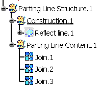
The Parting Line Content geometrical set contains the current elements of the parting line, presently the Reflect line.
- Its dialog box is initialized with the current data.
-
You do not require all the elements of the Reflect line to create the Parting Line.
Click to launch the Parting Line Selector . This command
enables you to select the elements you want to keep.
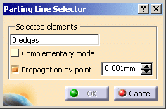
Make sure the Propagation by point check box is selected, and pick the elements you want to keep as follows:
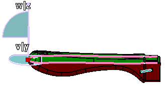
The elements that are contiguous within the value specified are selected in one shot.
The check box Complementary mode enables you to invert your selection.
Click OK to validate your choice and exit the dialog box.
The Reflect line has been moved to the Construction geometrical set and hidden.
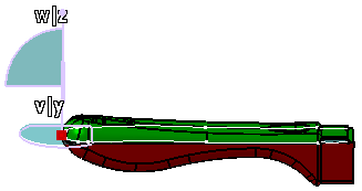
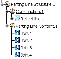
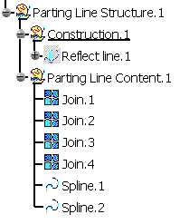
The Parting Line Content now contains three joins, corresponding to your three picks.
-
Now you need to create the parting line at the end of the panhandle.
Click to
launch the Chaining Edges
command.
Initialize the dialog box as follows:
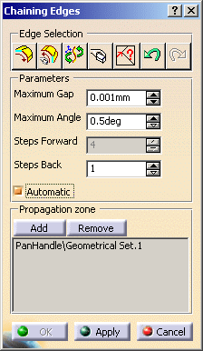
and select the edges as follows:
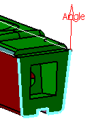
Click OK to validate your choice and exit the dialog box.
The Parting Line now looks like this
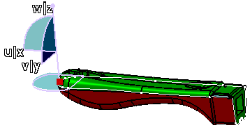
A join has been added to the Parting Line Content
-
Now, you need to fill the holes in the Parting Line.
Click to launch the
Spline command.
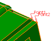
In the Spline Definition dialog box, select the Geometry on support check box
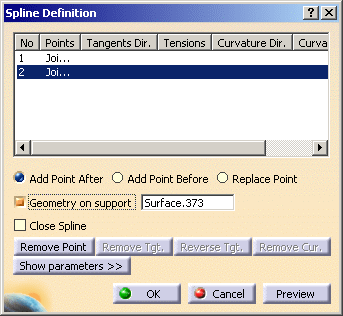
and select the following points:
Click OK.
Repeat the operation for the other two points:
Two Spline elements have been added to the Parting Line Content
-
Click OK in the Parting line dialog box to validate the Parting Line and exit the action.
![]()