|
|
This task shows you how to manage characteristic curves. | |
|
|
Characteristic curves are displayed in the folded and/or unfolded view of the part. They can be selected, though not edited, and used as a support (to create points for example). Characteristic curves can be computed for surfacic flanges or stamping features with a fillet. . |
|
Available characteristic curvesThe following characteristic curves can be computed on both folded and unfolded view, except when otherwise specified:
|
||
Features which support characteristic curvesCharacteristic curves can be computed for the following features:
|
||
|
|
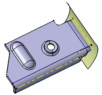
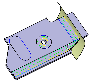
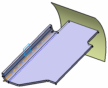
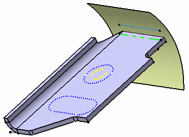
Open the CharacteristicCurves1.CATPart document. This sample includes two surfacic flanges, a bead and a flanged hole. All characteristic curves are put in show in the following images. |
|
Characteristic curves computed on the folded view |
||
 |
||
 |
||
Characteristic curves computed on the unfolded view |
||
 |
||
More about characteristic curves |
||
Standard management of characteristic curvesAdministrators can now customize characteristic curves through standards:
Refer to the Administration Tasks chapter for more information on this subject. Characteristic curves and settingsAs a user, you can manage the visibility of characteristic curves in folded and unfolded 3D views through settings. Refer to Display in the Customizing chapter for more information. |
||
Characteristic curves in hybrid design contextIn hybrid design context, if you define a feature as a Working object in the specification tree, the characteristic curves of features created after the Defined In Work Object are not displayed anymore on the geometry. |
||
 Surfacic Flange.1 defined as a Working object on a hybrid part. |
||
| Yet if you perform the same action on a part created prior to R14, the characteristic curves of features created after the Defined In Work Object remain visible. | ||
 Surfacic Flange.1 defined as a Working object on a non-hybrid part. |
||
| For more information about Hybrid Design, refer to the Hybrid Design section in the Part Design User's Guide. | ||
|
|
||