This task shows you how to report data into a flat table of tab-delimiting text.
A .CATProduct document must be
loaded.
You can also use the
ABF_AllTypeFast_01.CATProduct document.
-
Select the joint elements for which you wish to generate a report. The elements and the parent of higher level are selected.
You can select them either in the specification tree or in the 3D geometry.If you select a joint or a joint body, its children fasteners are highlighted in the specification tree. 
You can modify the selection once in the command. -
Click BiW flat reporting
 from the BiW Fasteners Report sub-toolbar.
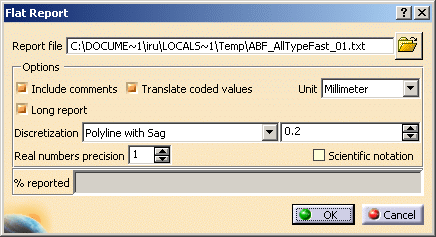
The Flat Report dialog box opens. The directory for the report file is the one defined in Customizing General Settings.
You can modify the path by clicking the Browse icon. The Select Report file dialog box displays letting you choose the file.
The dialog box enables you to customize the report through several options: -
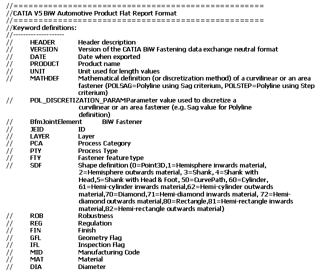
Include comments: the report will start with the commented header block showing keywords description.
-
Long report: projection results for all fasteners and specific data for each curve bead and spot projection fastener
- Translate coded values: attribute values belonging to a predefined list of codes are translated according to the NLS set-up. For instance if the value of the joint element's finish attribute is "B", on using this option will be displayed with the translation "Class B" in the report.
- Unit: either be millimeter or inch.
- Discretization:
- Polyline with sag: define the sag value used in the exported file.
- Polyline with step: define the step value used in the exported file.
- Real numbers precision: number of decimal digits of all the real numbers written in the neutral file and of the discretization values displayed in the dialog box above. This number is between 0 and 10.
- Scientific notation: it will be used in the report (power of 10)
-
-
Click OK.
The progress bar shows you the remaining exported percentage. -
Open the .txt file.
It displays: - one row per exported fastener containing all its attributes plus its parents ones.
- the joint element data (ID, type, diameter, etc...).
- the parents data (Joint Body ID, Joint ID).
- the joint crossed thicknesses information (count, part number, material).

Fasteners belonging to a same process type or process category are displayed in the same order as they appear in the specification tree. 
General Structure of the Flat Report

Structure of the Commented Block
The flat report begins with an optional commented block containing the following information: - A comprehensive description of the keywords used as column titles:

- Some header information such as the product name and the report date issue:

-
The column titles as keywords described above:
Version 3 Version 3.1 
Version 5 
Structure of the Results Block
The flat report contains different attributes which are spread over tab separated columns: - Fastener's attributes
- ID, type, diameter, layer number, etc.
- Fasteners parent's attributes
- Joint and joint bodies
- Joined contact zone attributes
- Path ID, thickness, material, layer number, etc.
- Additional crossed thicknesses attributes (only in long
reports)
- PROJ, Normal and projection point coordinates
Values and order of the projection attributes depend on the thickness crossing computation. For further information about ordering, refer to the Ordering Thickness Crossing Criteria chapter.
- PROJ, Normal and projection point coordinates
- Curvilinear fasteners discretization attributes (only in long
reports)
- Point Count, for each point the localization coordinates (X, Y, Z), the reference normal (W) and the tangent vector (U) coordinates.
- Projection fasteners attributes (only in long reports)
- ID, Projection zone

- You can only report BiW objects.
- A warning message
is diaplayed in case errors occur during the report process. They are
logged in a .xml file.
Refer to the Import chapter for more information. - One single log file is issued per flat report.
- Deactivated features are not reported; they appear in the log file.
- A selection of BiW fasteners to be reported can be made prior to entering the command. This selection can be modified at all time within the command.
- If no BiW entity is selected, the flat report will contain all fasteners found in the active product, including those located within all sub-product instances. In this case, the whole product structure is scanned recursively, starting from the active product.
- The products coordinates are reported relatively to the active product coordinates.
- The header always displays the active product information even if the report deals with an assembly.
![]()