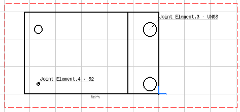
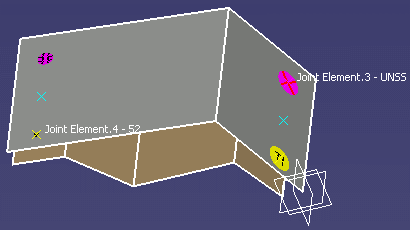
- Make sure the Prevent generative view style usage option is deselected from Tools > Options > Mechanical Design > Drafting > Administration tab if you wish to be able to create and use generative view styles.
GVS are documented in ABF Generative parameters.
- Make sure the spot fasteners have a normal vector orientation.
Refer to BiW Fastening Application Display User Settings for more information.
Case A: Drafting View without associated GVS The 3D Spot Fasteners will be generated in this view according to the Extract parameters in Tools > Options > Shape > Automotive BiW Fastening > General tab (Angular Tolerance, Include View Reverse Direction)
Case B: Drafting View with an associated GVS
- Providing that the Angular Tolerance is specified (different from -1)
The 3D Spot Fasteners will be generated in this View according to the Extract parameters in GVS (Angular Tolerance, Include View Reverse Direction)- Providing that the Angular Tolerance is not specified (set to -1)
The 3D Spot Fasteners will be generated in this View according to the Extract parameters in Tools > Options > Shape > Automotive BiW Fastening > General Tab (Angular Tolerance, Include View Reverse Direction)Example 1:
Providing that:
- the Angular Tolerance is different from -1 in the GVS parameters (45 for instance),
- the Include View Reverse Direction option is checked in the GVS parameters,
- the Angular Tolerance is set to 60 in Tools > Options (value not effective here),
- the Include View Reverse Direction option is unchecked in Tools > Options (value not effective here),
=> the 2D reverse spots will be generated in the Drawing document according to the GVS parameters (with Angular Tolerance value = 45).
Example 2:
- Providing that:
the Angular Tolerance is set to -1 in the GVS parameters (value not effective here),- the Include View Reverse Direction option is set to No in the GVS parameters (value not effective here),
- the Angular Tolerance is 45 in Tools > Options,
- the Include View Reverse Direction option is checked in Tools > Options,
=> the 2D reverse spots will be generated in the Drawing document according to Tools > Options parameters (with Angular Tolerance value = 45).
If the Angular Tolerance is set to 0 (through GVS or Tools > Options > Shape > Automotive BiW Fastening > General Tab), no 3D Spot Fastener will be generated on the Drawing View.
-
Click Top View
 from the Quick View toolbar.
 -
Select File > New from the menu bar.
The New dialog box opens. -
Select Drawing from the List of Types and click OK.
The New Drawing dialog box opens. -
Click OK.
The Generative Drafting workbench is displayed with a default grid. -
Select Window > Tile Horizontally from the menu bar to organize your windows horizontally.
-
In the drawing document, click Front View
 from the View toolbar (Quick View sub-toolbar).
The Generative view style toolbar is automatically displayed.
-
Select DefaultGenerativeStyle in the combo list.

-
Select the surface in the 3D document.
-
Click on the drawing sheet or at the center of the blue knob to generate the view.


- The visualization of the fastener in the drawing depends on the direction of the K-Axis in the 3D area. If the orientation of the K-axis is towards the surfaces included in the joint body, then the joint elements are visible in the front view of the drawing. If the orientation of the K-axis is opposite to the surfaces, then the joint elements are visible in back view of the drawing. You can rotate the drawing using the arrows in the blue knob so as to get the right view that shows the fastener 2D symbol.
- You can set a fixed size for your 2D drawing spots.
Refer to the General Settings chapter in the Customizing section.
If no size is specified then the spot diameters (2D Spot Symbol Diameter = 3D Spot Diameter) are respected in the 2D drawing document. - The fastener 2D representation is coherent with its 3D
representation:
- the fastener 2D symbol is visualized in the 2D drawing document view providing its 3D symbol is in show (see Editing Fasteners' Properties).
- the 2D fastener text is visualized providing the 3D text
is in show (see Editing Fasteners'
Properties).

Symbols are gathered together in the ABF_Symbols.CATDrawing reference file located according to the startup/components/Automotive BiW Fastening path from CATIA run time view root directory (intel_a for Windows, aix_a for IBM UNIX, irix_a for SGI UNIX, solaris_a for SUN Unix, hpux_a for HP UNIX). Here are these symbols: 2D symbol 3D symbol code 

111 

112 

113 

114 

151 

152 

153 

154 

136 

137 

138 

139 

101 

125 

155 

252 
any other 3D symbol
![]()
