To configure IP Security, tunnels and filters must be configured. When a simple tunnel is defined for all traffic to use, the filter rules can be automatically generated. If more complex filtering is desired, filter rules can be configured separately.
You can configure IP Security using the Web-based System Manager Network plug-in, Virtual Private Network plug-in, or the System Management Interface Tool (SMIT). If using SMIT, the following fast paths are available:
Before configuring IP Security for your site, you must decide what method you intend to use; for example, whether you prefer to use tunnels or filters (or both), which type of tunnel best suits your needs, and so on. The following sections provide information you must understand before making these decisions:
The 10/100 Mbps Ethernet PCI Adapter II (Feature code 4962) offers standards-based IP Security and is designed to offload IP Security functions from the AIX operating system. When the 10/100 Mbps Ethernet PCI Adapter II is present in the AIX system, the IP Security stack uses the following capabilities of the adapter:
The functions on the adapter are used instead of the software algorithms. The 10/100 Mbps Ethernet PCI Adapter II is available for manual and IKE tunnels.
The IP Security hardware acceleration feature is available in the 5.1.0.25 or later level of the bos.net.ipsec.rte and devices.pci.1410ff01.rte filesets.
There is a limit on the number of security associations that can be offloaded to the network adapter on the receive side (inbound traffic). On the transmit side (outbound traffic), all packets that use a supported configuration are offloaded to the adapter. Some tunnel configurations can not be offloaded to the adapter.
The 10/100 Mbps Ethernet PCI Adapter II supports the following:
To enable the 10/100 Mbps Ethernet PCI Adapter II for IP Security, you may have to detach the network interface and then enable the IPsec Offload feature.
To detach the network interface, do the following using the SMIT interface:
To enable the IPsec Offload feature, do the following using the SMIT interface:
To detach the network interface, from the command line, type the following:
# ifconfig enX detach
To enable the IPsec offload attribute, from the command line, type the following:
# chdev -l entX -a ipsec_offload=yes
To verify that the IPsec offload attribute has been enabled, from the command line, type the following:
# lsattr -El entX detach
To disable the IPsec offload attribute, from the command line, type the following:
# chdev -l entX -a ipsec_offload=no
Use the enstat command to ensure that your tunnel configuration is taking advantage of the IPsec offload attribute. The enstat command shows all the statistics of transmit and receive IPsec packets when the IPsec offload attribute is enabled. For example, if the Ethernet interface is ent1, type the following:
# entstat -d ent1
The output will be similar to the following:
.
.
.
10/100 Mbps Ethernet PCI Adapter II (1410ff01) Specific Statistics:
--------------------------------------------
.
.
.
Transmit IPsec packets: 3
Transmit IPsec packets dropped: 0
Receive IPsec packets: 2
Receive IPsec packets dropped: 0
Two distinct parts of IP Security are tunnels and filters. Tunnels require filters, but filters do not require tunnels.
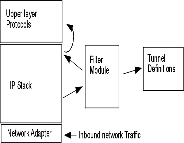
The following illustration indicates how a packet comes in from the network adapter to the IP stack. From there, the filter module is called to determine if the packet is permitted or denied. If a tunnel ID is specified, the packet is checked against the existing tunnel definitions. If the decapsulation from the tunnel is successful, the packet is passed to the upper-layer protocol. This function occurs in reverse order for outgoing packets. The tunnel relies on a filter rule to associate the packet with a particular tunnel, but the filtering function can occur without passing the packet to the tunnel.
Tunnels are used whenever you need to have data authenticated, or authenticated and encrypted. Tunnels are defined by specifying a security association between two hosts. The security association defines the parameters for the encryption and authentication algorithms and characteristics of the tunnel. The following illustration shows a virtual tunnel between Host A and Host B.
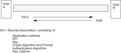
The Security Parameter Index (SPI) and the destination address identify a unique security association. These parameters are required for uniquely specifying a tunnel. Other parameters such as cryptographic algorithm, authentication algorithm, keys, and lifetime can be specified or defaults can be used.
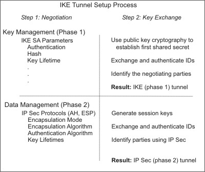
IKE tunnels differ from manual tunnels because the configuration of security policies is a separate process from defining tunnel endpoints. In IKE, there is a two-step negotiation process. Each step of the negotiation process is called a phase, and each phase can have separate security policies.
When the Internet Key negotiation starts, it must set up a secure channel for the negotiations. This is known as the key management phase or phase 1. During this phase, each party uses preshared keys or digital certificates to authenticate the other and pass ID information. This phase sets up a security association during which the two parties determine how they plan to communicate securely and then which protections are to be used to communicate during the second phase. The result of this phase is an IKE or phase 1 tunnel.
The second phase is known as the data management phase or phase 2 and uses the IKE tunnel to create the security associations for AH and ESP that actually protect traffic. The second phase also determines the data that will be using the IP Security tunnel. For example, it can specify the following:
In many cases, the endpoints of the key management (IKE) tunnel will be the same as the endpoints of the data management (IP Security) tunnel. The IKE tunnel endpoints are the IDs of the machines carrying out the negotiation. The IP Security tunnel endpoints describe the type of traffic that will use the IP Security tunnel. For simple host-to-host tunnels, in which all traffic between two tunnels is protected with the same tunnel, the phase 1 and phase 2 tunnel endpoints are the same. When negotiating parties are two gateways, the IKE tunnel endpoints are the two gateways, and the IP Security tunnel endpoints are the machines or subnets (behind the gateways) or the range of addresses (behind the gateways) of the tunnel users.
Phase 1 (the key management phase) sets the following parameters of an IKE tunnel configuration:
| Key Management
(Phase 1) Tunnel |
Name of this IKE tunnel. For each tunnel, the endpoints of the negotiation must be specified. These are the two machines that plan to send and validate IKE messages. The name of the tunnel may describe the tunnel endpoints such as VPN Boston or VPN Acme. |
| Host Identity Type | ID type that will be used in the IKE exchange. The ID type and value must match the value for the preshared key to ensure that proper key lookup is performed. If a separate ID is used to search a preshared key value, the host ID is the key's ID and its type is KEY_ID. The KEY_ID type is useful if a single host has more than one preshared key value. |
| Host Identity | Value of the host ID represented as an IP address, a fully qualified domain name (FQDN), or a user at the fully qualified domain name (user@FQDN). For example, jdoe@studentmail.ut.edu. |
| IP Address | IP address of the remote host. This value is required when the host ID type is KEY_ID or whenever the host ID type cannot be resolved to an IP address. For example, if the user name cannot be resolved with a local nameserver, the IP address for the remote side must be entered. |
You can customize key-management policy by specifying the parameters to be used during IKE negotiation. For example, there are key-management policies for preshared key or signature mode authentication. For Phase 1, the user must determine certain key-management security properties with which to carry out the exchange.
The data management proposal parameters are set during phase 2 of an IKE tunnel configuration. They are the same IP Security parameters used in manual tunnels and describe the type of protection to be used for protecting data traffic in the tunnel. You can start more than one phase 2 tunnel under the same phase 1 tunnel.
The following endpoint ID types describe the type of data that uses the IP Security Data tunnel:
| Host, Subnet, or Range | Describes whether the data traffic traveling in the tunnel will be for a particular host, subnet, or address range. |
| Host/Subnet ID | Contains the host or subnet identity of the local and remote systems passing traffic over this tunnel. Determines the IDs sent in the phase 2 negotiation and the filter rules that will be built if the negotiation is successful. |
| Subnet mask | Describes all IP addresses within the subnet (for example, host 9.53.250.96 and mask 255.255.255.0) |
| Starting IP Address Range | Provides the starting IP address for the range of addresses that will be using the tunnel (for example, 9.53.250.96 of 9.53.250.96 to 9.53.250.93) |
| Ending IP Address Range | Provides the ending IP address for the range of addresses that will be using the tunnel (for example, 9.53.250.93 of 9.53.250.96 to 9.53.250.93) |
| Port | Describes data using a specific port number (for example, 21 or 23) |
| Protocol | Describes data being transported with a specific protocol (for example, TCP or UDP). Determines the protocol sent in the phase 2 negotiation and the filter rules that will be built if the negotiation is successful. The protocol for the local endpoint must match the protocol for the remote end point. |
The decision to use manual tunnels or IKE tunnels depends on the tunnel support of the remote end and the type of key management desired. IKE tunnels are recommended (when available) because they offer industry-standard secure key negotiation and key refreshment. They also take advantage of the IETF ESP and AH header types and support anti-replay protection. You can optionally configure signature mode to allow digital certificates.
If the remote end uses one of the algorithms requiring manual tunnels, manual tunnels should be used. Manual tunnels ensure interoperability with a large number of hosts. Because the keys are static and difficult to change and might be cumbersome to update, they are not as secure. Manual tunnels can be used between a host running this operating system and any other machine running IP Security and having a common set of cryptographic and authentication algorithms. Most vendors offer Keyed MD5 with DES, or HMAC MD5 with DES. This subset works with almost all implementations of IP Security.
The procedure used in setting up manual tunnels, depends on whether you are setting up the first host of the tunnel or setting up the second host, which must have parameters matching the first host setup. When setting up the first host, the keys can be autogenerated, and the algorithms can be defaulted. When setting up the second host, import the tunnel information from the remote end, if possible.
Another important consideration is determining whether the remote system is behind a firewall. If it is, the setup must include information about the intervening firewall.
One common scenario for using IP Security with an operating system is when remote systems are initiating IKE sessions with a server and their identity cannot be tied to a particular IP address. This case can occur in a Local Area Network (LAN) environment, such as using IP Security to connect to a server on a LAN and wanting to encrypt the data. Other common uses involve remote clients dialing into a server, and using either a fully qualified domain name (FQDN) or e-mail address (user@FQDN) to identify the remote ID.
In order to make a policy decision based on explicit information about the remote identity, aggressive mode must be used. In this case, the identity is sent in the first message of the negotiation and can be used to do a policy lookup on the security policy database. This will ensure that only specifically named remote identities will be able to negotiate using the IKE protocol.
For the Data Management phase (Phase 2), when the IP Security associations are being created to encrypt TCP or UDP traffic, a generic data manager tunnel can be configured. Therefore, any request that was authenticated during phase 1, will use the generic tunnel for defined Data Management phase if the IP address is not explicitly configured in the database. This allows any address to match the generic tunnel and can be used as long as the rigorous public key-based security validation was successful in phase 1.
You can define a generic Data Management tunnel using the XML format understood by ikedb. Generic Data Management tunnels are used with DHCP. The XML format uses the tag name IPSecTunnel for what Web-based System Manager calls a Data Management tunnel. This is also referred to as a phase 2 tunnel in other contexts. A generic Data Management tunnel is not a true tunnel, but an IPSecProtection that is used if an incoming Data Management message (under a specific Key Management tunnel) does not match any Data Management tunnel defined for that Key Management tunnel. It is only used in the case where the AIX system is the responder. Specifying a generic Data Management tunnel IPSecProtection is optional.
The generic Data Management tunnel is defined in the IKEProtection element. There are two XML attributes, called IKE_IPSecDefaultProtectionRef and IKE_IPSecDefaultAllowedTypes, that are used for this.
First, you need to define an IPSecProtection that you would like to use as the default if no IPSecTunnels (Data Management tunnels) match. An IPSecProtection that is to be used as a default must have an IPSec_ProtectionName that begins with _defIPSprot_.
Now go to the IKEProtection that you would like to use this default IPSecProtection. Specify an IKE_IPSecDefaultProtectionRef attribute that contains the name of the default IPSec_Protection.
You must also specify a value for the IKE_IPSecDefaultAllowedTypes attribute in this IKEProtection. It can have one or more of the following values (if multiple values, they should be space-separated):
  Local_IPV4_Address
  Local_IPV6_Address
  Local_IPV4_Subnet
  Local_IPV6_Subnet
  Local_IPV4_Address_Range
  Local_IPV6_Address_Range
  Remote_IPV4_Address
  Remote_IPV6_Address
  Remote_IPV4_Subnet
  Remote_IPV6_Subnet
  Remote_IPV4_Address_Range
  Remote_IPV6_Address_Range
These values correspond to the ID types specified by the initiator. In the IKE negotiation, the actual IDs are ignored. The specified IPSecProtection is used if the IKE_IPSecDefaultAllowedTypes attribute contains a string beginning with Local_ that corresponds to the initiator's local ID type, and contains a string beginning with Remote_ that corresponds to the initiator's remote ID type. In other words, you must have at least one Local_ value and at least one Remote_ value in any IKE_IPSecDefaultAllowedTypes attribute in order for the corresponding IPSec_Protection to be used.
An initiator sends the following to the AIX system in a phase 2 (Data Management) message:
  local ID type:    IPV4_Address
  local ID:         192.168.100.104

  remote ID type:   IPV4_Subnet
  remote ID:        10.10.10.2
  remote netmask:   255.255.255.192
The AIX system does not have a Data Management tunnel matching these IDs. But it does have an IPSecProtection with the following attributes defined:
  IKE_IPSecDefaultProtectionRef="_defIPSprot_protection4"
  IKE_IPSecDefaultAllowedTypes="Local_IPV4_Address
                                Remote_IPV4_Address
                                Remote_IPV4_Subnet
                                Remote_IPV4_Address_Range"
The local ID type of the incoming message, IPV4_Address, matches one of the Local_ values of the allowed types, Local_IPV4_Address. Also, the remote ID of the message, IPV4_Subnet, matches the value Remote_IPV4_Subnet. Therefore the Data Management tunnel negotiation will proceed with _defIPSprot_protection4 as the IPSecProtection.
The /usr/samples/ipsec/default_p2_policy.xml file is a full XML file defining a generic IPSecProtection that can be used as an example.