[ Previous | Next | Table of Contents | Index | Library Home |
Legal |
Search ]
Performance Management Guide
The optimal settings of the tunable communications parameters vary with the
type of LAN, as well as with the communications-I/O characteristics of the
predominant system and application programs. The following sections
describe the global principles of communications tuning, followed by specific
recommendations for the different types of LAN.
You can choose to tune primarily either for maximum throughput or for
minimum memory use. Some recommendations apply to one or the
other; some apply to both. Recommended application block sizes for
different adapter devices are as follows:
| Device Name
| Application Block Size
|
| Ethernet
| Multiples of 4096
|
| Token-Ring (4 Mb)
| Multiples of 4096
|
| Token-Ring (16 Mb)
| Multiples of 4096
|
| FDDI (tcp)
| Multiples of 4096
|
| SOCC (tcp)
| 28672 bytes
|
| HIPPI
| 65536 bytes
|
| ATM
| Multiples of 4096
|
Use the following recommendations to tune for maximum throughput:
Follow these guidelines:
- For maximum number of transactions per second, use the smallest feasible
messages.
- For maximum bytes per second, use messages that are at least 1000 bytes
and equal to or just less than a multiple of 4096 bytes.
- If the requests and responses are fixed-size and fit into one datagram,
use UDP.
- If the requests or responses are variable-size, use TCP with the
TCP_NODELAY option. Measurements indicate that the overhead of TCP
compared with UDP is negligible, especially if optimum write sizes are
used.
- To avoid data copies in the kernel, make write sizes greater than 512
bytes.
- Make writes equal to or slightly less than, a multiple of MTU size.
This will avoid the sending of a segment (packet) with just a few bytes in
it.
Follow these guidelines:
- TCP provides higher throughput than UDP and ensures reliable
delivery.
- Writes should be in multiples of 16384 bytes. If possible, writes
should be the size of the MSS (see Tuning TCP Maximum Segment
Size).
Use the following recommendations to tune for minimizing memory
usage:
- If your traffic is predominantly local, use the largest MTU size that is
supported by your LAN type. This minimizes the fragmentation of packets
exchanged by local systems. The offsetting cost is fragmentation in
gateways that connect your LAN to other LANs with smaller MTUs (see Tuning TCP Maximum Segment Size).
- Whenever possible, application programs should read and write in
quantities of either:
- Less than or equal to 512 bytes
OR
- Slightly less than or equal to 4096 bytes (or multiples thereof)
If the applications were using TCP, both time and memory would be
wasted. TCP tries to form outbound data into MTU-sized packets.
If the MTU of the LAN were larger than 14976 bytes, TCP would put the sending
thread to sleep when the tcp_sendspace limit was reached.To
force the data to be written, a timeout ACK from the receiver would be
required.
Most communication drivers provide a set of tunable parameters to control
transmit and receive resources. These parameters typically control the
transmit queue and receive queue limits, but may also control the number and
size of buffers or other resources. These parameters limit the number
of buffers or packets that may be queued for transmit or limit the number of
receive buffers that are available for receiving packets. These
parameters can be tuned to ensure enough queueing at the adapter level to
handle the peak loads generated by the system or the network.
Following are some general guidelines:
- Tune transmit queues when the CPU is faster than the network (more common
on multi-processor systems where many CPUs are transmitting to a single
adapter).
- Tune transmit queues when socket buffer sizes are large.
- Tune receive queues when there is very bursty traffic.
- Tune transmit and receive queues when there is high rate of small-sized
packets.
For transmit, the device drivers may provide a transmit queue
limit. There may be both hardware queue and software queue limits,
depending on the driver and adapter. Some drivers have only a hardware
queue; some have both hardware and software queues. Some drivers
internally control the hardware queue and only allow the software queue limits
to be modified. Generally, the device driver will queue a transmit
packet directly to the adapter hardware queue. If the system CPU is
fast relative to the speed of the network, or on an SMP system, the system may
produce transmit packets faster than they can be transmitted on the
network. This will cause the hardware queue to fill. After the
hardware queue is full, some drivers provide a software queue and they will
then queue to the software queue. If the software transmit queue limit
is reached, then the transmit packets are discarded. This can affect
performance because the upper-level protocols must then time out and
retransmit the packet.
Prior to AIX 4.2.1, the upper limits on the transmit queues
were in the range of 150 to 250, depending on the specific adapter. The
system default values were low, typically 30. With AIX
4.2.1 and later, the transmit queue limits were increased on
most of the device drivers to 2048 buffers. The default values were
also increased to 512 for most of these drivers. The default values
were increased because the faster CPUs and SMP systems can overrun the smaller
queue limits.
Following are examples of MCA adapter transmit queue sizes:
| MCA Adapter Type
| Default
| Range
|
| Ethernet
| 512
| 20 - 2048
|
| 10/100 Ethernet
| 64
| 16,32,64,128,256
|
| Token-Ring
| 99 or 512
| 32 - 2048
|
| FDDI
| 512
| 3 - 2048
|
| ATM / 155 ATM
| 512
| 0 - 2048
|
Following are examples of PCI adapter transmit queue sizes:
| PCI Adapter Type
| Default
| Range
|
| Ethernet
| 64
| 16 - 256
|
| 10/100 Ethernet
| 256, 512, or 2048
| 16 -16384
|
| Token-Ring
| 96, 512, or 2048
| 32 - 16384
|
| FDDI
| 30 or 2048
| 3 - 16384
|
| 155 ATM
| 100 or 2048
| 0 - 16384
|
For adapters that provide hardware queue limits, changing these values will
cause more real memory to be consumed on receives because of the associated
control blocks and buffers associated with them. Therefore, raise these
limits only if needed or for larger systems where the increase in memory use
is negligible. For the software transmit queue limits, increasing these
limits does not increase memory usage. It only allows packets to be
queued that were already allocated by the higher layer protocols.
Some adapters allow you to configure the number of resources used for
receiving packets from the network. This might include the number of
receive buffers (and even their size) or may be a receive queue parameter
(which indirectly controls the number of receive buffers).
The receive resources may need to be increased to handle peak bursts on the
network. The network interface device driver places incoming packets on
a receive queue. If the receive queue is full, packets are dropped and
lost, resulting in the sender needing to retransmit. The receive queue
is tunable using the SMIT or chdev commands (see How to Change the Parameters). The maximum queue size
is specified to each type of communication adapter (see Tuning MCA and PCI Adapters).
For the Micro Channel adapters and the PCI adapters, receive queue
parameters typically control the number of receive buffers that are provided
to the adapter for receiving input packets.
AIX 4.1.4 and later support device-specific mbufs.
This allows a driver to allocate its own private set of buffers and have them
pre-setup for Direct Memory Access (DMA). This can provide additional
performance because the overhead to set up the DMA mapping is done one
time. Also, the adapter can allocate buffer sizes that are best suited
to its MTU size. For example, ATM, High Performance Parallel Interface
(HIPPI), and the SP switch support a 64 K MTU (packet) size. The
maximum system mbuf size is 16 KB. By allowing the adapter to have 64
KB buffers, large 64 K writes from applications can be copied directly into
the 64 KB buffers owned by the adapter, instead of copying them into multiple
16 K buffers (which has more overhead to allocate and free the extra
buffers).
The adapters that support Device Specific mbufs are:
- MCA ATM
- MCA HIPPI
- Various SP high speed switch adapters
Device-specific buffers add an extra layer of complexity for the system
administrator. The system administrator must use device-specific
commands to view the statistics relating to the adapter's buffers and
then change the adapter's parameters as necessary. If the
statistics indicate that packets were discarded because not enough buffer
resources were available, then those buffer sizes need to be increased.
Due to differences between drivers and the utilities used to alter these
parameters, the utilities and parameters are not fully described here.
The MCA ATM parameters are listed in Micro Channel Adapter
(MCA). Use the atmstat -d atm0 command to view the ATM
statistics (substitute your ATM interface number as needed).
Following are some guidelines to help you determine when to increase the
receive/transmit queue parameters:
- When the CPU is much faster than the network and multiple applications may
be using the same network. This would be common on a larger
multi-processor system (SMP).
- When running with large values for tcp_sendspace or
tcp_recvspace as set in the no options or running
applications that might use system calls to increase the TCP send and receive
socket buffer space. These large values can cause the CPU to send down
large numbers of packets to the adapter, which will need to be queued.
Procedures are similar for udp_sendspace and
udp_recvspace for UDP applications.
- When there is very bursty traffic.
- A high-traffic load of small packets can consume more resources than a
high traffic load of large buffers. Because large buffers take more
time to send on the network. The packet rate will therefore be slower
for larger packets.
Several status utilities can be used to show the transmit queue high-water
limits and number of queue overflows. You can use the command
netstat -v, or go directly to the adapter statistics utilities
(entstat for Ethernet, tokstat for Token-Ring,
fddistat for FDDI, atmstat for ATM, and so on).
For an entstat example output, see The entstat
Command. Another method is to use the netstat -i
utility. If it shows non-zero counts in the Oerrs column for
an interface, then this is typically the result of output queue
overflows.
You can use the lsattr -E -l adapter-name command or
you can use the SMIT command (smitty commodev) to show the adapter
configuration.
Different adapters have different names for these variables. For
example, they may be named sw_txq_size, tx_que_size, or
xmt_que_size for the transmit queue parameter. The receive
queue size and receive buffer pool parameters may be named
rec_que_size, rx_que_size, or rv_buf4k_min
for example.
Following is the output of a lsattr -E -l atm0 command on an IBM
PCI 155 Mbs ATM adapter. This output shows the sw_txq_size
is set to 250 and the rv_buf4K_min receive buffers set to
x30.
# lsattr -E -l atm0
dma_mem        0x400000    N/A                                          False
regmem         0x1ff88000  Bus Memory address of Adapter Registers      False
virtmem        0x1ff90000  Bus Memory address of Adapter Virtual Memory False
busintr        3           Bus Interrupt Level                          False
intr_priority  3           Interrupt Priority                           False
use_alt_addr   no          Enable ALTERNATE ATM MAC address             True
alt_addr       0x0           ALTERNATE ATM MAC address (12 hex digits)  True
sw_txq_size  250         Software Transmit Queue size                 True
max_vc         1024        Maximum Number of VCs Needed                 True
min_vc         32          Minimum Guaranteed VCs Supported             True
rv_buf4k_min 0x30        Minimum 4K-byte pre-mapped receive buffers   True
interface_type 0           Sonet or SDH interface                       True
adapter_clock  1           Provide SONET Clock                          True
uni_vers       auto_detect N/A                                          True
Following is an example of a Micro Channel 10/100 Ethernet settings using
the lsattr -E -l ent0 command. This output shows the
tx_que_size and rx_que_size both set to 256.
# lsattr -E -l ent0
bus_intr_lvl  11              Bus interrupt level                False
intr_priority 3               Interrupt priority                 False
dma_bus_mem   0x7a0000        Address of bus memory used for DMA False
bus_io_addr   0x2000          Bus I/O address                    False
dma_lvl       7               DMA arbitration level              False
tx_que_size 256             TRANSMIT queue size                True
rx_que_size 256             RECEIVE queue size                 True
use_alt_addr  no              Enable ALTERNATE ETHERNET address  True
alt_addr      0x              ALTERNATE ETHERNET address         True
media_speed   100_Full_Duplex Media Speed                        True
ip_gap        96              Inter-Packet Gap                   True
The following are some of the parameters that are user-configurable:
- Transmit Queue Size (tx_que_size)
The device driver supports a user-configurable transmit queue. This
is the queue the adapter uses (not an extension of the adapter's
queue). It is configurable among the values of 16, 32, 64, 128 and 256,
with a default of 256.
Because of the configurable size of the adapter's hardware queue, the
driver does not support a software queue.
- Receive Queue Size (rx_que_size)
The device driver supports a user-configurable receive queue. This
is the queue the adapter uses (not an extension of the adapter's
queue). It is configurable among the values of 16, 32, 64, 128 and 256,
with a default of 256.
- Receive Buffer Pool Size (rxbuf_pool_size)
The device driver supports a user-configurable receive buffer pool
size. The buffer is the number of preallocated mbufs for receiving
packets. The minimum size of the buffer is the receive queue size and
the maximum is 2 KB (the default value of 384).
- Media Speed (media_speed)
The device driver supports speeds of 10 (10 Mbps, half-duplex), 20 (10
Mbps, full-duplex), 100 (100 Mbps, half-duplex), 200 (100 Mbps, full-duplex),
and auto-negotiate on twisted pair. On the AUI port, the device driver
supports speeds of 10 (10 Mbps, half-duplex) and 20 (10 Mbps,
full-duplex). The bayonet Niell-Concelman (BNC) port will only support
10 (10 Mbps, half-duplex). This attribute is user-configurable, with a
default of auto-negotiate on twisted pair.
- Enable Alternate Address (use_alt_addr)
The device driver supports a configuration option to toggle use of an
alternate network address. The values are yes and no, with a default of
no. When this value is set to yes, the alt_addr parameter
defines the address.
- Alternate Network Address (alt_addr)
For the network address, the device driver accepts the adapter's
hardware address or a configured alternate network address. When the
use_alt_addr configuration option is set to yes, this alternate
address is used. Any valid individual address can be used, but a
multicast address cannot be defined as a network address.
- Inter-Packet Gap (ip_gap)
The inter-packet gap (IPG) bit rate setting controls the aggressiveness of
the adapter on the network. A smaller number will increase the
aggressiveness of the adapter, while a larger number will decrease the
aggressiveness (and increase the fairness) of the adapter. If the
adapter statistics show a large number of collisions and deferrals, increase
this number. Valid values range from 96 to 252, in increments of
4. The default value of 96 results in IPG of 9.6 microseconds
for 10 Mb and 0.96 microseconds for 100 Mb media speeds. Each
unit of bit rate introduces an IPG of 100 ns at 10 Mb and 10 ns at 100 Mb
media speed.
To change any of the parameter values, do the following:
- Detach the interface by running the following command:
# ifconfig en0 detach
where en0 represents the adapter name.
- Use SMIT to display the adapter settings. Select Devices ->
Communications -> adapter type ->
Change/Show...
- Move the cursor to the field you want to change, and press F4 to see the
minimum and maximum ranges for the field (or the specific set of sizes that
are supported).
- Select the appropriate size, and press Enter to update the ODM
database.
- Reattach the adapter by running the following command:
# ifconfig en0 hosthame up
An alternative method to change these parameter values is to run the
following command:
# chdev -l [ifname] -a [attribute-name]=newvalue
For example, to change the above tx_que_size on en0 to 128, use
the following sequence of commands. Note that this driver only supports
four different sizes, so it is better to use the SMIT command to see these
values.
# ifconfig en0 detach
# chdev -l ent0 -a tx_que_size=128
# ifconfig en0 hostname up
The following information is provided to document the various
adapter-tuning parameters. These parameters and values are for AIX
4.3.1 and are provided to aid you in understanding the various
tuning parameters, or when a system is not available to view the
parameters.
These parameter names, defaults, and range values were obtained from the
ODM database. The comment field was obtained from the lsattr -E
-l interface-name command.
The Notes field provides additional comments.
Feature Code:  2980
Ethernet High-Performance LAN Adapter (8ef5)

Parameter      Default  Range    Comment                     Notes
------------- -------- -------- --------------------------- -----------------
xmt_que_size   512     20-2048   TRANSMIT queue size        SW TX queue
rec_que_size   30      20-150    RECEIVE queue size         See Note 1
rec_pool_size  37      16-64     RECEIVE buffer pool size   On Adapter


Feature Code: 2992
Ethernet High-Performance LAN Adapter (8f95)

Parameter      Default   Range   Comment              Notes
------------- --------- -------- -------------------  ----------
xmt_que_size   512      20-2048  TRANSMIT queue size  SW queue


Feature Code: 2994
IBM 10/100 Mbps Ethernet TX MCA Adapter (8f62)

Parameter      Default  Range             Comment               Notes
------------- -------- ----------------  --------------------- -----------
tx_que_size   64       16,32,64,128,256  TRANSMIT queue size    HW queue
rx_que_size   32       16,32,64,128,256  RECEIVE queue size     HW queue


Feature Code: 2970
Token-Ring High-Performance Adapter (8fc8)

Parameter      Default  Range    Comment                 Notes
------------- -------- --------  ---------------------  ------------
xmt_que_size  99       32-2048   TRANSMIT queue size     SW queue
rec_que_size  30       20-150    RECEIVE queue size      See Note 1


Feature Code: 2972
Token-Ring High-Performance Adapter (8fa2)

Parameter      Default  Range    Comment                      Notes
------------- -------- -------- ----------------------------  ----------
xmt_que_size  512      32-2048  TRANSMIT queue size           SW queue
rx_que_size   32       32-160   HARDWARE RECEIVE queue size   HW queue


Feature Code: 2727
FDDI Primary Card, Single Ring Fiber

Parameter      Default  Range    Comment                        Notes
------------- -------- --------  ------------------------------ --------------------
tx_que_size   512      3-2048    Transmit Queue Size (in mbufs)
rcv_que_size  30       20-150    Receive Queue                  See Note 1


Feature Code: 2984
100 Mbps ATM Fiber Adapter (8f7f)

Parameter       Default Range   Comment                    Notes
--------------- ----- --------- -------------------------- -----
sw_queue        512   0-2048    Software transmit queue len.  SW Queue
dma_bus_width   0x1000000 0x800000-0x40000000,0x100000  Amount of memory to map for DMA  See Note 3
max_sml_bufs    50    40-400    Maximum Small ATM mbufs    Max 256 byte buffers
max_med_bufs    100   40-1000   Maximum Medium ATM mbufs   Max 4KB buffers
max_lrg_bufs    300   75-1000   Maximum Large ATM mbufs    Max 8KB buffers See Note 2
max_hug_bufs    50    0-400     Maximum Huge ATM mbufs     Max 16KB buffers
max_spec_bufs   4     0-400     Maximum ATM MTB mbufs  Max of max_spec_buf size
spec_buf_size   64    32-1024   Max Transmit Block (MTB) size (kbytes)
sml_highwater   20    10-200    Minimum Small ATM mbufs    Min 256 byte buffers
med_highwater   30    20-300    Minimum Medium ATM mbufs   Min 4KB buffers
lrg_highwater   70    65-400    Minimum Large ATM mbufs    Min 8KB buffers
hug_highwater   10    4-300     Minimum Huge ATM mbufs     Min 16KB buffers
spec_highwater  20    0-300     Minimum ATM MTB mbufs      Min 64KB buffers
best_peak_rate  1500  1-155000  Virtual Circuit Peak Segamentation Rate


Feature Code: 2989
155 Mbps ATM Fiber Adapter (8f67)

Parameter      Default   Range     Comment    Notes
------------- --------  --------  ---------- -------
 (same as ATM 100 adapter above)
Notes:
- A software receive queue is provided only for compatibility with operating
system version 3.2.x applications that use the network device
driver interface to read packets directly from the driver. This queue
limits how many input packets are queued for these applications to
receive. This parameter is defined only if bos.compat
is installed.
This queue is not used by the typical TCP/IP stack.
- MCA ATM: The receive side also uses the large (8 K) buffers.
The receive logic only uses the 8 K buffers, so if this size runs low, it
affects receive performance.
The other buffers sizes are only for transmit buffers.
- MCA ATM: If you need to increase the total number of buffers, you
may need to change the dma_bus_width (= 0x1000000)
parameter. DMA bus memory width controls the total amount of memory
used for ATM buffers. Increase this parameter if you get an error while
you are increasing the maximum buffers or high-water limits.
Feature Code 2985
IBM PCI Ethernet Adapter (22100020)

Parameter      Default  Range            Comment             Notes
------------- -------- ----------------- ------------------- ---------
tx_que_size   64       16,32,64,128,256  TRANSMIT queue size HW Queues
rx_que_size   32       16,32,64,128,256  RECEIVE queue size  HW Queues


Featue Code 2968
IBM 10/100 Mbps Ethernet PCI Adapter (23100020)

Parameter        Default Range            Comment               Notes
---------------- ------- ---------------- --------------------- --------------------
tx_que_size      256     16,32,64,128,256 TRANSMIT queue size   HW Queue Note 1
rx_que_size      256     16,32,64,128,256 RECEIVE queue size    HW Queue Note 2
rxbuf_pool_size  384     16-2048          # buffers in receive  Dedicat. receive
                                          buffer pool           buffers Note 3


Feature Code: 2969
Gigabit Ethernet-SX PCI Adapter (14100401)

Parameter     Default Range    Comment                             Notes
------------- ------- -------- ----------------------------------- ---------
tx_que_size   512     512-2048 Software Transmit Queueu size       SW Queue
rx_que_size   512     512      Receive queue size                  HW Queue
receive_proc  6       0-128    Minimum Receive Buffer descriptiors


Feature Code: 2986
3Com 3C905-TX-IBM Fast EtherLink XL NIC

Parameter      Default  Range  Comment                      Notes
-------------- -------- ------ ---------------------------- ----------
tx_wait_q_size 32       4-128  Driver TX Waiting Queue Size HW Queues
rx_wait_q_size 32       4-128  Driver RX Waiting Queue Size HW Queues


Feature Code: 2742
SysKonnect PCI FDDI Adapter (48110040)

Parameter     Default  Range    Comment             Notes
------------- -------- -------- ------------------- ---------------
tx_queue_size 30       3-250    Transmit Queue Size SW Queue
RX_buffer_cnt 42       1-128    Receive frame count Rcv buffer pool


Feature Code: 2979
IBM PCI Tokenring Adapter (14101800)

Parameter     Default  Range   Comment                     Notes
------------- -------- ------- --------------------------- --------
xmt_que_size  96       32-2048 TRANSMIT queue size         SW Queue
rx_que_size   32       32-160  HARDWARE RECEIVE queue size HW queue


Feature Code: 2979
IBM PCI Tokenring Adapter (14103e00)

Parameter     Default  Range    Comment              Notes
------------- -------- -------- -------------------- --------
xmt_que_size  512      32-2048  TRANSMIT queue size  SW Queue
rx_que_size   64       32-512   RECEIVE queue size   HW Queue


Feature Code: 2988
IBM PCI 155 Mbps ATM Adapter (14107c00)

Parameter     Default   Range        Comment                          Notes
------------- --------- ------------ -------------------------------- --------
sw_txq_size   100       0-4096       Software Transmit Queue size     SW Queue
rv_buf4k_min  48 (0x30) 0-512 (x200) Minimum 4K-byte pre-mapped receive buffers
Notes on the IBM 10/100 Mbps Ethernet PCI Adapter:
- Prior to AIX 4.3.2, default tx_queue_size was
64.
- Prior to AIX 4.3.2, default rx_que_size was
32.
- In AIX 4.3.2 and later, the driver added a new parameter to
control the number of buffers dedicated to receiving packets.
Drivers, by default, call IP directly, which calls up the protocol stack to
the socket level while running on the interrupt level. This minimizes
instruction path length, but increases the interrupt hold time. On an
SMP system, a single CPU can become the bottleneck for receiving packets from
a fast adapter. By enabling the dog threads, the driver
queues the incoming packet to the thread and the thread handles calling IP,
TCP, and the socket code. The thread can run on other CPUs which may be
idle. Enabling the dog threads can increase capacity of the system in
some cases.
Note: This feature is not supported on uniprocessors, because
it would only add path length and slow down performance.
This is a feature for the input side (receive) of LAN adapters. It
can be configured at the interface level with the ifconfig command
(ifconfig interface thread or
ifconfig interface hostname up
thread).
To disable the feature, use the ifconfig interface
-thread command.
Guidelines when considering using dog threads are as follows:
The TCP protocol includes a mechanism for both ends of a connection to
negotiate the maximum segment size (MSS) to be used over the
connection. Each end uses the OPTIONS field in the TCP header to
advertise a proposed MSS. The MSS that is chosen is the smaller of the
values provided by the two ends.
The purpose of this negotiation is to avoid the delays and throughput
reductions caused by fragmentation of the packets when they pass through
routers or gateways and reassembly at the destination host.
The value of MSS advertised by the TCP software during connection setup
depends on whether the other end is a local system on the same physical
network (that is, the systems have the same network number) or whether it is
on a different (remote) network.
If the other end of the connection is local, the MSS advertised by TCP is
based on the MTU (maximum transfer unit) of the local network interface, as
follows:
TCP MSS = MTU - TCP header size - IP header size.
Because this is the largest possible MSS that can be accommodated without
IP fragmentation, this value is inherently optimal, so no MSS-tuning is
required for local networks.
When the other end of the connection is on a remote network, this operating
system's TCP defaults to advertising an MSS of 512 bytes. This
conservative value is based on a requirement that all IP routers support an
MTU of at least 576 bytes.
The optimal MSS for remote networks is based on the smallest MTU of the
intervening networks in the route between source and destination. In
general, this is a dynamic quantity and could only be ascertained by some form
of path MTU discovery. The TCP protocol, by default, does not provide a
mechanism for doing path MTU discovery, which is why a conservative MSS value
is the default. However, it is possible to enable the TCP PMTU
discovery by using the following command:
# no -o tcp_pmtu_discover=1
MTU path discovery was added to AIX 4.2.1, but the default is
off. With AIX 4.3.3 and later, the default is on.
A typical side effect of this setting is to see the routing table
increasing (one more entry per each active TCP connection). The
no option route_expire should be set to a non-zero
value, in order to have any unused cached route entry removed from the table,
after route_expire time of inactivity.
While the conservative default is appropriate in the general Internet, it
can be unnecessarily restrictive for private Intranets within an
administrative domain. In such an environment, MTU sizes of the
component physical networks are known, and the minimum MTU and optimal MSS can
be determined by the administrator. The operating system provides
several ways in which TCP can be persuaded to use this optimal MSS.
Both source and destination hosts must support these features. In a
heterogeneous, multi-vendor environment, the availability of the feature on
both systems can determine the choice of solution.
The default MSS of 512 can be overridden by specifying a static route to a
specific remote network. Use the -mtu option of the
route command to specify the MTU to that network. In this
case, you would specify the actual minimum MTU of the route, rather than
calculating an MSS value.
In a small, stable environment, this method allows precise control of MSS
on a network-by-network basis. The disadvantages of this approach are
as follows:
- It does not work with dynamic routing.
- It becomes impractical when the number of remote networks
increases.
- Static routes must be set at both ends to ensure that both ends negotiate
with a larger-than-default MSS.
This parameter is used to set the maximum packet size for communication
with remote networks. However, only one value can be set even if there
are several adapters with different MTU sizes. The default value of 512
that TCP uses for remote networks can be changed via the no
command. This change is a systemwide change.
To override the MSS default specify a value that is the minimum MTU value
less 40 to allow for the typical length of the TCP and IP headers.
The size is the same as the MTU for communication across a local network
with one exception: the tcp_mssdflt size is only for the size
of the data in a packet. Reduce the tcp_mssdflt for the size
of any headers so that you send full packets instead of a full packet and a
fragment. Calculate this as follows:
MTU of interface - TCP header size - IP header size - rfc1323 header size
which is:
MTU - 20 - 20 - 12, or MTU - 52
Limiting data to (MTU - 52) bytes ensures that, where possible, only full
packets will be sent.
In an environment with a larger-than-default MTU, this method has the
advantage in that the MSS does not need to be set on a per-network
basis. The disadvantages are as follows:
- Increasing the default can lead to IP router fragmentation if the
destination is on a network that is truly remote and the MTUs of the
intervening networks are not known.
- The tcp_mssdflt parameter must be set to the same value on the
destination host.
Several physical networks can be made to share the same network number by
subnetting. The no option subnetsarelocal
specifies, on a systemwide basis, whether subnets are to be considered local
or remote networks. With the command no -o subnetsarelocal=1
(the default), Host A on subnet 1 considers Host B on subnet 2 to be on the
same physical network.
The consequence is that when Host A and Host B establish a connection, they
negotiate the MSS assuming they are on the same network. Each host
advertises an MSS based on the MTU of its network interface, usually leading
to an optimal MSS being chosen.
The advantages to this approach are as follows:
- It does not require any static bindings; MSS is automatically
negotiated.
- It does not disable or override the TCP MSS negotiation, so that small
differences in the MTU between adjacent subnets can be handled
appropriately.
The disadvantages to this approach are as follows:
- Potential IP router fragmentation when two high-MTU networks are linked
through a lower-MTU network. The following figure illustrates this
problem.
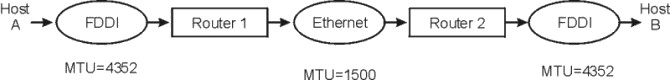
Figure 9-3. Inter-Subnet Fragmentation. This illustration show a data path from Host A, through an FDDI with an MTU=4352, through Router 1, to the Ethernet with an MTU=1500. From there it goes to Router 2 and another FDDI with an MTU=4352 and out to Host B. An explanation of how fragmentation occurs in this example is described in the text immediately following the illustration.
- In this scenario, Hosts A and B would establish a connection based on a
common MTU of 4352. A packet going from A to B would be fragmented by
Router 1 and defragmented by Router 2. The reverse would occur going
from B to A.
- Source and destination must both consider subnets to be local.
UDP is a datagram protocol. Being a datagram, the entire message
(datagram) must be copied into the kernel on a send operation as one atomic
operation. The maximum amount of data that UDP can send at one time is
limited by the size of the memory buffer assigned to a specific UDP socket,
and the maximum packet size that the IP layer can handle in each
packet.
Set this parameter to 65536, because any value greater than 65536 is
ineffective. Because UDP transmits a packet as soon as it gets any
data, and because IP has an upper limit of 65536 bytes per packet, anything
beyond 65536 runs the small risk of being discarded by IP. The IP
protocol will fragment the datagram into smaller packets if needed, based on
the MTU size of the interface the packet will be sent on. For example,
sending an 8 K datagram, IP would fragment this into 1500 byte packets if sent
over Ethernet. Because UDP does not implement any flow control, all
packets given to UPD are passed to IP (where they may be fragmented) and then
placed directly on the device drivers transmit queue.
On the receive side, the incoming datagram (or fragment if the datagram is
larger than the MTU size) will first be received into a buffer by the device
driver. This will typically go into a buffer that is large enough to
hold the largest possible packet from this device.
The setting of udp_recvspace is harder to compute because it
varies by network adapter type, UDP sizes, and number of datagrams queued to
the socket. Set the udp_recvspace larger rather than
smaller, because packets will be discarded if it is too small.
For example, Ethernet might use 2 K receive buffers. Even if the
incoming packet is maximum MTU size of 1500 bytes, it will only use 73 percent
of the buffer. IP will queue the incoming fragments until a full UDP
datagram is received. It will then be passed to UDP. UDP will
put the incoming datagram on the receivers socket. However, if the
total buffer space in use on this socket exceeds udp_recvspace,
then the entire datagram will be discarded. This is indicated in the
output of the netstat -s command as dropped due to full socket
buffers errors.
Because the communication subsystem accounts for buffers used, and not the
contents of the buffers, you must account for this when setting
udp_recvspace. In the above example, the 8 K datagram would
be fragmented into 6 packets which would use 6 receive buffers. These
will be 2048 byte buffers for Ethernet. So, the total amount of socket
buffer consumed by this one 8 K datagram is as follows:
6*2048=12,288 bytes
Thus, you can see that the udp_recvspace must be adjusted higher
depending on how efficient the incoming buffering is. This will vary by
datagram size and by device driver. Sending a 64 byte datagram would
consume a 2 K buffer for each 64 byte datagram.
Then, you must account for the number of datagrams that may be queued onto
this one socket. For example, NFS server receives UDP packets at one
well-known socket from all clients. If the queue depth of this socket
could be 30 packets, then you would use 30 * 12,288 = 368,640 for the
udp_recvspace if NFS is using 8 K datagrams. NFS Version 3
allows up to 32K datagrams.
A suggested starting value for udp_recvspace is 10 times the
value of udp_sendspace, because UDP may not be able to pass a
packet to the application before another one arrives. Also, several
nodes can send to one node at the same time. To provide some staging
space, this size is set to allow 10 packets to be staged before subsequent
packets are discarded. For large parallel applications using UDP, the
value may have to be increased.
Note: The value of sb_max, which specifies the
maximum socket buffer size for any socket buffer, should be at least twice the
size of the largest of the UDP and TCP send and receive buffers.
The following table shows some suggested minimum sizes for
socket buffers based on the type of adapter and the MTU size. Note that
setting these values too high can hurt performance. In addition, there
is the Nagle Black hole problem that can cause very low throughput
for large MTU adapters, such as ATM if the TCP send and receive space
parameters are not chosen correctly.
| Device
| Speed
| MTU
| tcp_sendspace
| tcp_recvspace
| sb_max
| rfc1323
|
| Ethernet
| 10 Mbit
| 1500
| 16384
| 16384
| 32768
| 0
|
| Ethernet
| 100 Mbit
| 1500
| 16384
| 16384
| 32768
| 0
|
| Ethernet
| Gigabit
| 1500
| 65535
| 16384
| 131072
| 0
|
| Ethernet
| Gigabit
| 9000
| 131072
| 65535 (Note 1)
| 262144
| 0
|
| Ethernet
| Gigabit
| 9000
| 131072
| 92160 (Note 1)
| 262144
| 1
|
| ATM
| 155 Mbit
| 1500
| 16384
| 16384
| 131072
| 0
|
| ATM
| 155 Mbit
| 9180
| 65535
| 65535 (Note 2)
| 131072
| 0
|
| ATM
| 155 Mbit
| 65527
| 655360
| 655360 (Note 3)
| 1310720
| 1
|
| FDDI
| 100 Mbit
| 4352
| 45056
| 45056
| 90012
| 0
|
- Note 1:
- In the case of Gigabit Ethernet with a 9000 byte MTU, the performance was
the same for both given sets of buffer sizes.
- Note 2:
- Certain combinations of TCP send and receive space will result in very low
throughput (1 Mbit or less). This problem is described in detail in
How a Large ATM MTU Causes Deadlocks in TCP Data Transfers,
IEEE/ACM Transactions on Networking, Vol. 3, No.4 August 1995
and TCP Buffering and Performance over an ATM Network,
Internetworking: Research and Experience, Vol. 6 1-13,
1995.
To avoid this problem, set the tcp_sendspace to a minimum of 3
times the MTU size or equal or larger than the receivers
tcp_recvspace. For example, on ATM with MTU 9180, a
tcp_sendspace of 16384 and a tcp_recvspace of 32768 or
65536 resulted in very poor performance. However, setting both to 65536
resulted in excellent performance. Also, setting both equal to 16384
resulted in acceptable performance (the equal or larger rule).
- Note 3:
- TCP has only a 16-bit value to use for its window size. This
translates to a maximum window size of 65536 bytes. For adapters that
have large MTU sizes (32 K or 64 K for example), TCP streaming performance may
be very poor. For example, on a device with a 64 K MTU size, and with a
tcp_recvspace set to 64 K, TCP can only send one packet and then
its window will close. It must wait for an ACK back from the receiver
before it can send again. This problem can be solved in two ways:
One option is to enable rfc1323. This option enhances TCP
and allows it to overcome the 16 bit limit so that it can use a window size
larger than 64 Kb. You can then set the tcp_recvspace to a
large value such as 10 times the MTU size which will allow TCP to stream data
and give good performance.
The second option is to reduce the MTU size of the adapter. For
example, use the command ifconfig at0 mtu 16384 to set the ATM MTU
size to 16 K. This will cause TCP to compute a smaller MSS. With
a 16 K MTU size, it could still send 4 packets for a 64 K window size.
Following are some general guidelines:
- Set the TCP send/recv space to at least 10 times the MTU size.
- MTU sizes above 16 K should use rfc1323=1 to allow larger TCP
recvspace values.
- For high-speed adapters, larger TCP send/receive space values help
performance.
- The window size is the receiver's window size; therefore,
rfc1323 affects only the receiver.
- For the Gigabit Ethernet adapter increase the
tcp_sendspace. If the application gets blocked and is put to
sleep due to a small tcp_sendspace, there is too much latency on
wake up and sending the packets again to keep the adapter busy.
The ftp and rcp commands are examples of TCP
applications that benefit from tuning the tcp_sendspace and
tcp_recvspace variables.
TCP send buffer size can limit how much data the application can send
before the application is put to sleep. The TCP socket send buffer is
used to buffer the application data in the kernel using mbufs/clusters before
it is sent beyond the socket and TCP layer. The default size of this
buffer is specified by the parameter tcp_sendspace, but you can use
the setsockopt() subroutine to override it.
If the amount of data that the application wants to send is smaller than
the send buffer size and also smaller than the maximum segment size and if
TCP_NODELAY is not set, then TCP will delay up to 200 ms, until enough data
exists to fill the send buffer or the amount of data is greater than or equal
to the maximum segment size, before transmitting the packets.
If TCP_NODELAY is set, then the data is sent immediately (useful for
request/response type of applications). If the send buffer size is less
than or equal to the maximum segment size (ATM and SP switches can have 64 K
MTUs), then the application's data will be sent immediately and the
application must wait for an ACK before sending another packet (this prevents
TCP streaming and could reduce throughput).
Note: To maintain a steady stream of packets, increase the
socket send buffer size so that it is greater than the MTU (3-10 times the MTU
size could be used as a starting point).
If an application does nonblocking I/O (specified O_NDELAY or O_NONBLOCK on
the socket), then if the send buffer fills up, the application will return
with an EWOULDBLOCK/EAGAIN error rather than being put to sleep.
Applications must be coded to handle this error (suggested solution is to
sleep for a short while and try to send again).
When you are changing send/recv space values, in some cases you must
stop/restart the inetd process as follows:
# stopsrc -s inetd; startsrc -s inetd
TCP receive-buffer size limits how much data the receiving system can
buffer before the application reads the data. The TCP receive buffer is
used to accommodate incoming data. When the data is read by the TCP
layer, TCP can send back an acknowledgment (ACK) for that packet immediately
or it can delay before sending the ACK. Also, TCP tries to piggyback
the ACK if a data packet was being sent back anyway. If multiple
packets are coming in and can be stored in the receive buffer, TCP can
acknowledge all of these packets with one ACK. Along with the ACK, TCP
returns a window advertisement to the sending system telling it how much room
remains in the receive buffer. If not enough room remains, the sender
will be blocked until the application has read the data. Smaller values
will cause the sender to block more. The size of the TCP receive buffer
can be set using the setsockopt() subroutine or by the
tcp_recvspace parameter.
The TCP window size by default is limited to 65536 bytes (64 K) but can be
set higher if rfc1323 is set to 1. If you are setting
tcp_recvspace to greater than 65536, set rfc1323=1 on
each side of the connection. Without having rfc1323 set on
both sides, the effective value for tcp_recvspace will be
65536.
If you are sending data through adapters that have large MTU sizes (32 K or
64 K for example), TCP streaming performance may not be optimal because the
packet or packets will be sent and the sender will have to wait for an
acknowledgment. By enabling the rfc1323 option using the
command no -o rfc1323=1, TCP's window size can be set as high
as 4 GB. However, on adapters that have 64 K or larger MTUs, TCP
streaming performance can be degraded if the receive buffer can only hold 64
K. If the receiving machine does not support rfc1323, then
reducing the MTU size is one way to enhance streaming performance.
After setting the rfc1323 option to 1, you can increase the
tcp_recvspace parameter to something much larger, such as 10 times
the size of the MTU.
This parameter controls how much buffer space is consumed by buffers that
are queued to a sender's socket or to a receiver's socket.
The system accounts for socket buffers used based on the size of the buffer,
not on the contents of the buffer.
If a device driver puts 100 bytes of data into a 2048-byte buffer, then the
system considers 2048 bytes of socket buffer space to be used. It is
common for device drivers to receive buffers into a buffer that is large
enough to receive the adapters maximum size packet. This often results
in wasted buffer space but it would require more CPU cycles to copy the data
to smaller buffers.
Because there are so many different network device drivers, increase the
sb_max value much higher rather than making it the same as the
largest TCP or UDP socket buffer size parameters. After the total
number of mbufs/clusters on the socket reaches the sb_max limit, no
additional buffers can be queued to the socket until the application has read
the data.
Note: When you are setting buffer size parameters to larger
than 64 K, you must also increase the value of sb_max, which
specifies the maximum socket buffer size for any socket buffer.
One guideline would be to set it to twice as large as the largest TCP or
UDP receive space.
In AIX 4.3.3, a feature called Interface-Specific Network
Options (ISNO) was introduced that allows IP network interfaces to be
custom-tuned for the best performance. Values set for an individual
interface take precedence over the systemwide values set with the
no command. The feature is enabled (the default) or disabled
for the whole system with the no command use_isno
option. This single-point ISNO disable option is included as a
diagnostic tool to eliminate potential tuning errors if the system
administrator needs to isolate performance problems.
Programmers and performance analysts should note that the ISNO values will
not show up in the socket (meaning they cannot be read by the
getsockopt() system call) until after the TCP connection
is made. The interface this socket will actually be using is not known
until the connection is complete, so the socket reflects the system defaults
from the no command. After the connection is accepted, ISNO
values are put into the socket.
The following five parameters have been added for each supported network
interface:
- rfc1323
- tcp_nodelay
- tcp_sendspace
- tcp_recvspace
- tcp_mssdflt
When set for a specific interface, these values override the corresponding
no option values set for the system. These parameters are
available for all of the mainstream TCP/IP interfaces (Token-Ring, FDDI,
10/100 Ethernet, and Gigabit Ethernet), except the css#
IP interface on the SP switch. As a simple workaround, SP switch users
can set the tuning options appropriate for the switch using the systemwide
no command, then use the ISNOs to set the values needed for the
other system interfaces. ATM is supported and works correctly with AIX
4.3.3 (a software update is needed) and later.
These options are set for the TCP/IP interface (such as en0 or tr0), and
not the network adapter (ent0 or tok0).
The five new ISNO parameters cannot be displayed or changed using
SMIT. Following are commands that can be used first to verify system
and interface support and then to set and verify the new values.
- Make sure the use_isno option is enabled by using the following
command:
# no -a | grep isno
use_isno = 1
- Make sure the interface supports the five new ISNOs by using the
lsattr -El command:
# lsattr -E -l en0 -H
attribute     value description                                user_settable
:
rfc1323             N/A                                        True
tcp_nodelay         N/A                                        True
tcp_sendspace       N/A                                        True
tcp_recvspace       N/A                                        True
tcp_mssdflt         N/A                                        True
- Set the interface-specific values, using either the ifconfig or
chdev command. The ifconfig command sets values
temporarily (best used for testing). The chdev command
alters the ODM, so custom values return after system reboots.
For example, to set the tcp_recvspace and
tcp_sendspace to 64K and enable tcp_nodelay, use one of
the following methods:
# ifconfig en0 tcp_recvspace 65536 tcp_sendspace 65536 tcp_nodelay 1
OR
# chdev -l en0 -a tcp_recvspace=65536 -a tcp_sendspace=65536 -a tcp_nodelay=1
- Verify the settings using the ifconfig or lsattr
command:
# ifconfig en0
en0: flags=e080863<UP,BROADCAST,NOTRAILERS,RUNNING,SIMPLEX,MULTICAST,GROUPRT,64BIT>
        inet 9.19.161.100 netmask 0xffffff00 broadcast 9.19.161.255
        tcp_sendspace 65536 tcp_recvspace 65536 tcp_nodelay 1
OR
# lsattr -El en0
rfc1323                     N/A                                        True
tcp_nodelay   1             N/A                                        True
tcp_sendspace 65536         N/A                                        True
tcp_recvspace 65536         N/A                                        True
tcp_mssdflt                 N/A                                        True
At the IP layer, the only tunable parameter is ipqmaxlen, which
controls the length of the IP input queue discussed in IP
Layer. In AIX Version 4, in general, interfaces do not do
queuing. Packets can arrive very quickly and overrun the IP input
queue. You can use the netstat -s or netstat -p
ip command to view an overflow counter (ipintrq
overflows).
If the number returned is greater than 0, overflows have occurred.
Use the no command to set the maximum length of this queue.
For example:
# no -o ipqmaxlen=100
This example allows 100 packets to be queued up. The exact value to
use is determined by the maximum burst rate received. If this cannot be
determined, using the number of overflows can help determine what the increase
should be. No additional memory is used by increasing the queue
length. However, an increase may result in more time spent in the
off-level interrupt handler, because IP will have more packets to process on
its input queue. This could adversely affect processes needing CPU
time. The tradeoff is reduced packet-dropping versus CPU availability
for other processing. It is best to increase ipqmaxlen by
moderate increments if the tradeoff is a concern in your environment.
Ethernet is one of the contributors to the "least common denominator"
algorithm of MTU choice. If a configuration includes Ethernets and
other LANs, and there is extensive traffic among them, the MTUs of all of the
LANs may need to be set to 1500 bytes to avoid fragmentation when data enters
an Ethernet. Following are some guidelines:
- Do not change the default (and maximum) MTU of 1500 bytes.
- Set the application block size in multiples of 4096 bytes.
- Keep socket space settings at the default values.
- If the workload includes extensive use of services that use UDP, such as
NFS or RPC, increase sb_max to allow for the fact that each
1500-byte MTU uses a 4096-byte buffer.
The default MTU of 1492 bytes is appropriate for Token-Rings that
interconnect to Ethernets or to heterogeneous networks in which the minimum
MTU is not known. Following are some guidelines:
- Unless the LAN has extensive traffic to outside networks, raise the MTU to
the maximum of 3900 bytes.
- Application block size should be in multiples of 4096 bytes.
- Socket space settings can be left at the default values.
- If the workload includes extensive use of services that use UDP, such as
NFS or RPC, increase sb_max to allow for the fact that each
1492-byte MTU uses a 4096-byte buffer.
The default MTU of 1492 bytes is appropriate for Token-Rings that
interconnect to Ethernets or to heterogeneous networks in which the minimum
MTU is not known. Following are some guidelines:
- Unless the LAN has extensive traffic to outside networks, raise the MTU to
8500 bytes. This allows NFS 8 KB packets to fit in one MTU.
Further increasing the MTU to the maximum of 17000 bytes seldom results in
corresponding throughput improvement.
- Application block size should be in multiples of 4096 bytes.
- Socket space settings can be left at the default values.
- If the workload includes extensive use of services that use UDP, such as
NFS or RPC, and the MTU must be left at the default because of
interconnections, increase sb_max to allow for the fact that each
1492-byte MTU uses a 4096-byte buffer.
Despite the comparatively low MTU, this high-speed medium benefits from
substantial increases in socket buffer size. Following are some
guidelines:
- Unless the LAN has extensive traffic to outside networks, the default MTU
of 4352 bytes should be retained.
- Where possible, an application using TCP should write multiples of 4096
bytes at a time (preferably 8 KB or 16 KB) for maximum throughput.
- Use no -o *_*space=NewSize to set the TCP and UDP
socket send and receive space defaults to NewSize bytes.
NewSize should be at least 57344 bytes (56 KB).
- Use no -o sb_max=(2*NewSize) to increase the maximum
number of socket buffer space.
- For RS/6000 Model *90 or faster, use no -o rfc1323=1 to allow
socket buffer sizes to be set to more than 65536. Then use the previous
procedure with NewSize of at least 128 KB.
Following are some guidelines:
- Unless the LAN has extensive traffic to outside networks, retain the
default MTU of 9180 bytes. Where possible, an application using TCP
should write multiples of 4096 bytes at a time (preferably 8 KB or 16 KB) for
maximum throughput.
- Use no -o *_*space=NewSize to set the TCP and UDP
socket send and receive space defaults to NewSize bytes.
NewSize should be at least 57344 bytes (56 KB).
- Use no -o sb_max=(2*NewSize) to increase the maximum
number of socket buffer space.
- For RS/6000 Model *90 or faster, use no -o rfc1323=1 to allow
socket buffer sizes to be set to more than 65536. Then use the previous
procedure with NewSize of at least 128 KB.
Following are some guidelines:
- The default MTU 61428 bytes should not be changed.
- Where possible, an application using TCP should write 28672 bytes (28 KB)
at a time for maximum throughput.
- Set TCP and UDP socket send and receive space defaults to 57344
bytes.
Following are some guidelines:
- The default MTU of 65536 bytes should not be changed.
- Where possible, an application using TCP should write 65536 bytes at a
time for maximum throughput.
- Set sb_max to a value greater than 2 * 655360.
- TCP and UDP socket send and receive space defaults should be set to 655360
bytes. Use no -o rfc1323=1 to allow socket buffer sizes to
be set to more than 65536.
[ Previous | Next | Table of Contents | Index |
Library Home |
Legal |
Search ]