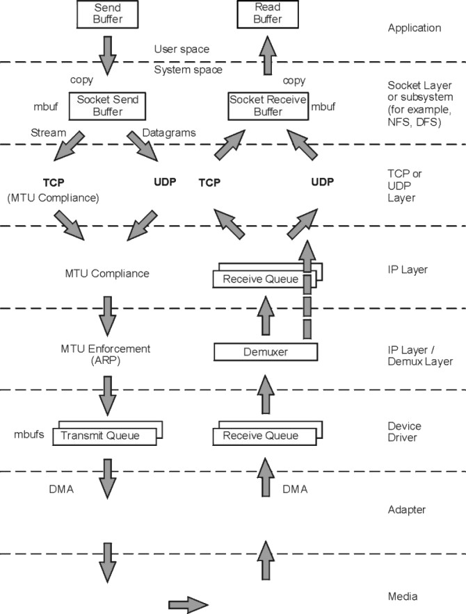
To understand the performance characteristics of UDP (user datagram protocol) and TCP/IP, you must first understand some of the underlying architecture. The following figure illustrates the structure that will be discussed in this chapter.
Figure 9-1. UDP and TCP/IP Data Flow. The figure shows the path of data from an application in one system to another application in a remote system. The steps of the data flow are described in the text immediately following the illustration.
|
The figure shows the path of data from an application in one system to another application in a remote system. The processing at each of the layers is discussed in this chapter, but key points are as follows:
To avoid fragmentation of kernel memory and the overhead of numerous calls to the xmalloc() subroutine, the various layers of the communication subsystem share common buffer pools. The mbuf management facility controls different buffer sizes. The pools consist of pinned pieces of kernel virtual memory; this means that they always reside in physical memory and are never paged out. The result is that the real memory available for paging in application programs and data has been decreased by the amount that the mbuf pools have been increased.
In addition to avoiding duplication, sharing the mbuf and cluster pools allows the various layers to pass pointers to one another, reducing mbuf management calls and copying of data.
For additional details, see Tuning mbuf Pool Performance.
Sockets provide the application program interface (API) to the communication subsystem. Several types of sockets provide various levels of service by using different communication protocols. Sockets of type SOCK_DGRAM use the UDP protocol. Sockets of type SOCK_STREAM use the TCP protocol.
The processes of opening, reading, and writing to sockets are similar to those for manipulating files.
The sizes of the buffers in system virtual memory (that is, the total number of bytes from the mbuf pools) that are used by the input and output sides of each socket are limited by system-wide default values (which can be overridden for a given socket by a call to the setsockopt() subroutine):
Use the following to display these values:
# no -a
A root user can set these values as follows:
# no -o udp_sendspace=NewValue
The NewValue parameter must be less than or equal to the sb_max parameter, which controls the maximum amount of space that can be used by a socket's send or receive buffer. The default value of the sb_max parameter depends on the operating system version and amount of real memory. The sb_max value is displayed with the command no -a and set with the no command, as follows:
# no -o sb_max=NewLimit
Note: Socket send or receive buffer sizes are limited to no more than sb_max bytes, because sb_max is a ceiling on buffer space consumption. The two quantities are not measured in the same way, however. The socket buffer size limits the amount of data that can be held in the socket buffers. The sb_max value limits the number of bytes of mbufs that can be in the socket buffer at any given time. In an Ethernet environment, for example, each 2048-byte mbuf cluster might hold just 1500 bytes of data. In that case, sb_max would have to be 1.37 times larger than the specified socket buffer size to allow the buffer to reach its specified capacity. The guideline is to set sb_max to at least twice the size of the largest socket buffer.
As an application writes to a socket, the socket layer calls the transport layer (either TCP or UDP), which copies the data from user space into the socket send buffer in kernel space. Depending on the amount of data being copied into the socket send buffer, the code puts the data into either mbufs or clusters.
On the receive side, an application opens a socket and attempts to read data from it. If there is no data in the socket receive buffer, the socket layer causes the application thread to go to the sleep state (blocking) until data arrives. When data arrives, it is put on the receive socket buffer queue and the application thread is made dispatchable. The data is then copied into the application's buffer in user space, the mbuf chain is freed, and control is returned to the application.
In AIX 4.3.1 and later, the sockthresh value determines how much of the system's network memory can be used before socket creation is disallowed. The value of sockthresh is given as a percentage of thewall. It has a default of 85 percent and can be set to any value from 1 to 100. However, sockthresh cannot be set to a value lower than the amount of memory currently in use.
The sockthresh option is intended to prevent situations where many connections are opened until all the network memory on the machine is used. This leaves no memory for other operations, and the machine hangs and must be rebooted to recover. Use sockthresh to set the point at which new sockets should not be allowed. Calls to the socket() and socketpair() subroutines will fail with an error of ENOBUFS, and incoming connection requests will be silently discarded. This allows the remaining network memory to be used by existing connections and prevents the machine from hanging.
The netstat -m statistic sockets not created because sockthresh was reached is incremented each time a socket creation fails because the amount of network memory already in use is over the sockthresh limit.
Use the following to display the sockthresh value:
# no -o sockthresh
A root user can set the value as follows:
# no -o sockthresh=NewValue
The default value can be set as follows:
# no -d sockthresh
When an application requests that the system assign the port (application is not requesting a specific port number), this is called an ephemeral port. Prior to AIX 4.3.1, the ephemeral port range was from 1024 to 5000. Starting with AIX 4.3.1, the default starting ephemeral port number is 32768, and the default largest ephemeral port number is 65535.
Using the no command, these values can be tuned with the tcp_ephemeral_low and tcp_ephemeral_high parameters. The maximum range would be to set tcp_ephemeral_low to 1024 and tcp_ephemeral_high to 65535. UDP ports have the same tunable parameters available through udp_ephemeral_low and udp_ephemeral_high (defaults are identical).
The following two sections contain descriptions of the function of UDP and TCP. To facilitate comparison of UDP and TCP, both descriptions are divided into subsections on connection, error detection, error recovery, flow control, data size, and MTU handling.
UDP provides a low-cost protocol for applications that have the facilities to deal with communication failures. UDP is most suitable for request-response applications. Because such an application has to handle a failure to respond anyway, it is little additional effort to handle communication error as one of the causes of failure to respond. For this reason, and because of its low overhead, subsystems such as NFS, ONC RPC, DCE RPC, and DFS use UDP.
Features of the UDP layer are as follows:
If udp_sendspace is large enough to hold the datagram, the application's data is copied into mbufs in kernel memory. If the datagram is larger than udp_sendspace, an error is returned to the application.
The operating system chooses optimum size buffers from a power of 2 size buffer. For example, a write of 8704 bytes is copied into two clusters, a 8192-byte and a 512-byte cluster. UDP adds the UDP header (in the same mbuf, if possible), checksums the data, and calls the IP ip_output() routine.
UDP verifies the checksum and queues the data onto the proper socket. If the udp_recvspace limit is exceeded, the packet is discarded. A count of these discards is reported by the netstat -s command under udp: as socket buffer overflows. If the application is waiting for a receive or read on the socket, it is put on the run queue. This causes the receive to copy the datagram into the user's address space and release the mbufs, and the receive is complete. Usually, the receiver responds to the sender to acknowledge the receipt and also return a response message.
In AIX 4.1.1 and later, UDP checksums the data "on the fly" when it copies it into the kernel mbuf. When receiving, this same optimization can be done, but the application must enable it with the SO_CKSUMRECV option on a setsockopt() call. Applications that receive large UDP buffers should program to use this option for better performance.
TCP provides a reliable transmission protocol. TCP is most suitable for applications that, at least for periods of time, are mostly output or mostly input. With TCP ensuring that packets reach their destination, the application is freed from error detection and recovery responsibilities. Applications that use TCP transport include ftp, rcp, and telnet. DCE can use TCP if it is configured to use a connection-oriented protocol.
Features of the TCP layer are as follows:
Figure 9-2. TCP Sliding Window. This illustration depicts the TCP Sliding Window. A full description is in the text immediately following the figure.
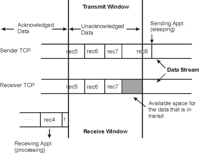 |
In this figure, the sending application is sleeping because it has attempted to write data that would cause TCP to exceed the send socket buffer space (that is, tcp_sendspace). The sending TCP still has the last part of rec5, all of rec6 and rec7, and the beginning of rec8. The receiving TCP has not yet received the last part of rec7 or any of rec8. The receiving application got rec4 and the beginning of rec5 when it last read the socket, and it is now processing that data. When the receiving application next reads the socket, it will receive (assuming a large enough read), the rest of rec5, rec6, and as much of rec7 and rec8 as has arrived by that time.
After the next read, the following occur:
The sending application will wake up. To avoid excessive LAN traffic when the application is reading in tiny amounts, TCP delays acknowledgment until the receiving application has read a total amount of data that is at least half the receive window size or twice the maximum segment size.
If there is no data to send back, the receiver will delay up to 200 ms and then send the ACK. The delay time can be tuned by a new no parameter called fasttimeo. The default value is 200 ms, and the range of values can be between 50 ms and 200 ms. Reducing this value may enhance performance of request/response type of applications.
Note: When using TCP to exchange request/response messages, the application must use the setsockopt() subroutine to turn on the TCP_NODELAY option. This causes TCP to send the message immediately (within the constraints of the sliding window), even though it is less than MTU-size. Otherwise, TCP would wait for up to 200 milliseconds for more data to send before transmitting the message. Starting with AIX 4.3.3 the tcp_nodelay parameter can be set with the ifconfig or chdev command to set TCP_NODELAY on TCP sockets (see Interface-Specific Network Options (ISNO)).
In the course of establishing a session, the initiator and the listener converse to determine the receive space for each end point. The size defines the size of the receive window. As data is written to the socket, it is moved into the sender's buffer. When the receiver indicates that it has space available, the sender transmits enough data to fill that space (assuming that it contains that much data). When the receiving application reads from the socket, the receiving socket returns as much data as it has in its receive socket buffer. TCP then informs the sender that the data has been successfully delivered by sending a packet to advance the receiver window. Only then does the sending TCP discard the data from its own buffer, effectively moving the window to the right by the amount of data delivered. If the window is full because the receiving application has fallen behind, the sending thread will be blocked (or receive a specific errno) when it tries to write to the socket.
The value of tcp_recvspace and tcp_sendspace are independent. The tcp_sendspace controls the buffering in the kernel of the sender. The tcp_recvspace controls the receiver space and translates into TCP's receive window.
If the rfc1323 parameter is 1, the maximum TCP window size is 4 GB (instead of 64 KB).
The additional operations performed by TCP to ensure a reliable connection result in about 5 to 10 percent higher processor cost than in UDP.
When the TCP layer receives a write request from the socket layer, it allocates a new mbuf for its header information and copies the data in the socket-send buffer either into the TCP-header mbuf, if there is room, or into a newly allocated mbuf chain. If the data being copied is in clusters, the data is not actually copied into new clusters. Instead, a pointer field in the new mbuf header (this header is part of the mbuf structure and is unrelated to the TCP header) is set to point to the clusters containing the data, thereby avoiding the overhead of one or more 4 KB copies. TCP then checksums the data (unless it is offloaded by certain PCI adapters), updates its various state variables, which are used for flow control and other services, and finally calls the IP layer with the header mbuf now linked to the new mbuf chain.
When the TCP input routine receives input data from IP, the following occur:
The Internet Protocol provides a basic datagram service to the higher layers. If it is given a packet larger than the MTU of the interface, it fragments the packet and sends the fragments to the receiving system, which reassembles them into the original packet. If one of the fragments is lost in transmission, the incomplete packet is ultimately discarded by the receiver. MTU path discovery can be enabled as described in Tuning TCP Maximum Segment Size.
The length of time IP waits for a missing fragment is controlled by the ipfragttl parameter, which is set and displayed with the no command.
Following are some default values and value ranges for different network
types:
| Network Type | Default (bytes) | Range (bytes) |
| X.25 | 576 | 60-2058 |
| SLIP | 1006 | 60-4096 |
| Standard Ethernet | 1500 | 60 - 1500 |
| IEEE 802.3 Ethernet | 1492 | 60 - 1492 |
| Gigabit Ethernet | 9000 (Jumbo Frames) | N/A |
| Token-Ring 4 Mbps | 1492 | 60 - 4096 |
| Token-Ring 16 Mbps | 1492 | 60 - 17800 |
| FDDI | 4352 | 1 - 4352 |
| SLA (socc) | 61428 | 1 - 61428 |
| ATM | 9180 | 1 - 65527 |
| HIPPI | 65536 | 60 - 65536 |
| SP Switch | 65520 | 1 - 65520 |
Note: In general, you can increase the transmit and receive queues. This requires some memory, but avoids some problems. See Adapter Transmit and Receive Queue Tuning.
When the IP output routine receives a packet from UDP or TCP, it identifies the interface to which the mbuf chain should be sent, updates and checksums the IP part of the header, and passes the packet to the interface (IF) layer.
IP determines the proper device driver and adapter to use, based on the network number. The driver interface table defines the maximum MTU for this network. If the datagram is less than the MTU size, IP adds the IP header in the existing mbuf, checksums the IP header, and calls the driver to send the frame. If the driver send queue is full, an EAGAIN error is returned to IP, which returns it to UDP, which returns it to the sending application. The sender should delay and try again.
If the datagram is larger than the MTU size (which only occurs in UDP), IP fragments the datagram into MTU-size fragments, appends a IP header (in an mbuf) to each, and calls the driver once for each fragment frame. If the driver's send queue is full, an EAGAIN error is returned to IP. IP discards all remaining unsent fragments associated with this datagram and returns EAGAIN to UDP. UDP returns EAGAIN the sending application. Since IP and UDP do not queue messages, it is up to the application to delay and try the send again.
In AIX Version 4, in general, interfaces do not perform queuing and directly call the IP input queue routine to process the packet; the loopback interface will still perform queuing. In the case of queuing, the demux layer places incoming packets on this queue. If the queue is full, packets are dropped and never reach the application. If packets are dropped at the IP layer, a statistic called ipintrq overflows in the output of the netstat -s command is incremented. If this statistic increases in value, then use the no command to tune the ipqmaxlen tunable.
In AIX Version 4, the demux layer (formerly called the IF layer) calls IP on the interrupt thread. IP checks the IP header checksum to make sure the header was not corrupted and determines if the packet is for this system. If so, and the frame is not a fragment, IP passes the mbuf chain to the TCP or UDP input routine.
If the received frame is a fragment of a larger datagram (which only occurs in UDP), IP retains the frame. When the other fragments arrive, they are merged into a logical datagram and given to UDP when the datagram is complete. IP holds the fragments of an incomplete datagram until the ipfragttl time (as specified by the no command) expires. The default ipfragttl time is 30 seconds (an ipfragttl value of 60). If any fragments are lost due to problems such as network errors, lack of mbufs, or transmit queue overruns, IP never receives them. When ipfragttl expires, IP discards the fragments it did receive. This is reported as a result from the netstat -s command. Under ip:, see fragments dropped after timeout.
The interface layer (IF) is used on output and is the same level as the demux layer (used for input) in AIX Version 4. It places transmit requests on to a transmit queue, where the requests are then serviced by the network interface device driver. The size of the transmit queue is tunable, as described in Adapter Transmit and Receive Queue Tuning.
When the demux layer receives a packet from IP, it attaches the link-layer header information to the beginning of the packet, checks the format of the mbufs to make sure they conform to the device driver's input specifications, and then calls the device driver write routine.
The address resolution protocol (ARP) is also handled in this layer. ARP translates a 32-bit Internet Protocol (IP) address into a 48-bit hardware address.
In AIX Version 4, when the demux layer receives a packet from the device driver, it calls IP on the interrupt thread to perform IP input processing.
If the dog threads are enabled (see Enabling Thread Usage on LAN Adapters (dog threads)), the incoming packet will be queued to the thread and the thread will handle calling IP, TCP, and the socket code.
The operating system environment supports many different kinds of LAN
adapters. You can choose from a wide variety of network
interfaces. As the following table shows, as the speed of these
networks varies, so does the performance.
| Name | Speed |
| Ethernet (en) | 10 Mbit/sec - Gigabits/sec |
| IEEE 802.3 (et) | 10 Mbit/sec - Gigabits/sec |
| Token-Ring (tr) | 4 or 16 Mbit/sec |
| X.25 protocol (xt) | 64 Kb/sec |
| Serial Line Internet Protocol, SLIP (sl) | 64 Kb/sec |
| loopback (lo) | N/A |
| FDDI (fi) | 100 Mbit/sec |
| SOCC (so) | 220 Mbit/sec |
| ATM (at) | 100s Mbit/sec (many Gb/sec) |
Refer to the PCI Adapter Placement Reference and RS/6000 Systems Handbook for slot placement guidelines and limitations that may exist on the number of adapters that can be supported for connectivity and the number that can be supported for maximum performance.
Several PCI machines have secondary PCI buses bridged onto a primary PCI bus. Some medium- to high-speed adapters perform slower on these secondary bus slots and some adapters are not recommended to be used in these slots. Machines with some secondary PCI slots include E30, F40, and SP 332 MHz SMP-wide nodes.
The adapters differ, not only in the communications protocol and transmission medium they support, but also in their interface to the I/O bus and the processor. Similarly, the device drivers vary in the technique used to convey the data between memory and the adapter. The following description of send and receive flow applies to most adapters and device drivers, but details vary.
At the device-driver layer, the mbuf chain containing the packet is enqueued on the transmit queue. The maximum total number of output buffers that can be queued is controlled by the system parameter xmt_que_size. In some cases, the data is copied into driver-owned DMA buffers. The adapter is then signaled to start DMA operations.
At this point, control returns up the path to the TCP or UDP output routine, which continues sending as long as it has data to send. When all data has been sent, control returns to the application, which then runs asynchronously while the adapter transmits data. Device driver dependent, when the adapter has completed transmission, it sends an interrupt to the system. When the interrupt is handled, the device-interrupt routines are called to adjust the transmit queues and free the mbufs that held the transmitted data.
When frames are received by an adapter, they are transferred from the adapter into a driver-managed receive queue. The receive queue can consist of mbufs or the device driver can manage a separate pool of buffers for the device. In either case, the data is in an mbuf chain when it is passed from the device driver to the demux layer.
Some drivers receive frames through Direct Memory Access (DMA) into a pinned area of memory and then allocate mbufs and copy the data into them. Drivers/adapters that receive large-MTU frames may have the frames accessed directly into cluster mbufs. The driver transfers the frame to the correct network protocol (IP in this example) by calling a demultiplexing function that identifies the packet type and puts the mbuf containing the buffer on the input queue for that network protocol. If no mbufs are available or if the higher-level input queue is full, the incoming frames are discarded.