This section contains information on the following frame buffer update topics:
Various writemasks control what data is stored in each bitplane of the frame buffer by shielding portions of the frame buffer from being written into. In color map mode, the writemask subroutine protects specified bitplanes from ordinary drawing routines. In RGB mode, the RGBwritemask subroutine performs this function. The zwritemask subroutine controls writing into the z-buffer. The logicop subroutine specifies the logical operation to use when writing pixels. The getwritemask subroutine and gRGBmask subroutine allow you to determine the current writemasks.
| blendfunction | |
| Specifies the alpha blending ratio. | |
| getwritemask | |
| Returns the current writemask. | |
| gRGBmask | |
| Returns the current RGB writemask. | |
| logicop | |
| Specifies a logical operation for pixel writes. | |
| RGBwritemask | |
| Grants write permission to a subset of available bitplanes (in RGB mode). | |
| wmpack | |
| Specifies an RGBA writemask with a single packed integer. | |
| writemask | |
| Grants write permission to a subset of available bitplanes in color map mode. | |
| zfunction | |
| Specifies the function used for depth comparison. | |
| zsource | |
| Selects depth or color as the source for z comparisons. | |
| zwritemask | |
| Specifies which bits of the z-buffer are written during normal z-buffer operation. | |
In all cases when the system uses color maps (the standard bitplanes in color map mode, and the overlay and underlay bitplanes), a writemask is available that can limit the drawing into the bitplanes. By default, the writemask is set up so that there are no drawing restrictions, but it is sometimes useful to limit the effects of the drawing routines. Two common cases are to provide the equivalent of extra overlay bitplanes and to display a layered scene where the contents of the layers are independent of each other.
The writemask is described in terms of the standard drawing bitplanes, but exactly the same comments are true if the system is in overlay or underlay mode. For this discussion, it is assumed that only 8 of the 12 bitplanes are used, although the discussion applies equally well to different numbers, including 24 bitplanes.
With 8 bitplanes, the color is a number from 0 to 255, which can be represented by 8 binary bits. For example, color 68 is 01000100 . Without writemask controls, if the color is set to 68, then every drawing subroutine puts 01000100 into the 8 bitplanes of the affected pixels.
A writemask restricts this overwriting. If, in the previous example, the writemask were 15 (= 00001111) , then only the bottom 4 bits of the color are written into the bitplanes (that is, with writemask, a 1 enables a bitplane for writing, and a 0 disables it). If the color is 68, then any pixels hit by a drawing subroutine would contain wxyz0100 , where wxyz are the 4 bits that were previously there. The 0s (zeros) in the writemask prevent those bits from being overwritten. The default writemask is entirely 1s, so there is no restriction.
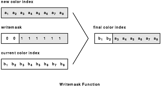
Writemasks determine whether a new value can be stored in each bitplane. A 1 (one) in the writemask allows the system to store a new value (0 or 1) in the corresponding bitplane. A 0 (zero) prevents the system from storing a new value, and the corresponding bitplane retains its current value.
In the figure, the values in the first and second bits (b1 and b2) do not change because the corresponding positions in the writemask are zero. All the other values (originally b3, b4, ...b8) change to a3, a4, ...a8 because the corresponding positions in the writemask are 1. Each value a1, ...a8 and b1, ...b8 is either 0 or 1, and the setting of the writemask determines whether the value is written.
As a very simple example, suppose you wish to draw two completely independent electronic circuits on the screen, power and ground. You would like the power grid to be drawn in blue, the ground grid to be drawn in black, and short-circuits (where both power and ground appear) to be drawn in red. The background color is white.
Initialize the program as follows:
#define BACKGROUND  0       /*=00*/
#define POWER       1       /*=01*/
#define GROUND      2       /*=10*/
#define SHORT       3       /*=11*/
mapcolor(0, 255, 255, 255); /*white*/
mapcolor(1, 0, 0, 255);     /*blue*/
mapcolor(2, 0, 0, 0);       /*black*/
mapcolor(3, 255, 0, 0);     /*red*/
Then draw all the power circuitry into bitplane 1 and the ground circuitry in bitplane 2. Where both power and ground appear, there is a 1 in both bitplanes, making color 3.
To clear the window before drawing:
writemask(3);
color(BACKGROUND);
clear();
To draw power circuitry without affecting ground circuitry:
writemask(1);
color(1);
<drawing subroutines>
To draw ground circuitry without affecting power circuitry:
writemask(2);
color(2);
<drawing subroutines>
writemask(1);
color(0);
clear();
To erase all ground circuitry:
writemask(2);
color(0);
clear();
The circuit.c example program demonstrates the use of writemasks by drawing power circuitry as previously discussed.
The writemask subroutine grants write permission to available bitplanes. It protects bitplanes, in the current drawing mode, that are reserved for special uses from ordinary drawing subroutines. The parameter is a mask with 1 bit available per bitplane.
Whenever there are 1s in the writemask, the corresponding bits in the color index are written into the bitplanes. Zeros in the writemask mark bitplanes as read-only. These bitplanes are not changed, regardless of the bits in the color index.
If the drawing mode is NORMALDRAW, the writemask affects the standard bitplanes; if the mode is OVERDRAW, the writemask affects the overlay bitplanes; if the mode is UNDERDRAW, the writemask affects the underlay bitplanes. Use the RGBwritemask subroutine in RGB mode.
It is very important to understand that with the writemask, the bit pattern at each pixel is additive. This means that although you can protect certain bits from being overwritten, all the bits at any pixel are still taken as a single integer or color index value. The syntax is as follows:
void writemask(Colorindex writem)
The getwritemask subroutine returns the current writemask of the current drawing mode. The writemask is an integer with up to 12 significant bits, one for each available bitplane. Use the gRGBmask subroutine in RGB mode. The syntax is as follows:
Int32 getwritemask()
The RGBwritemask subroutine is the same as the writemask subroutine, except it functions in RGB mode. The red, green, and blue parameters are masks for each of the three sets of bitplanes. In the same way that writemasks affect drawing in bitplanes in NORMALDRAW color map mode, separate red, green, and blue masks can be applied in NORMALDRAW RGB mode. The syntax is as follows:
void RGBwritemask(Int16 red, Int16 green, Int16 blue)
The gRGBmask subroutine returns the current RGB writemask as three 8-bit masks. This subroutine places masks in the low-order 8 bits of the locations pointed to by the redmask, greenmask, and bluemask parameters. The system must be in RGB mode when the gRGBmask subroutine executes. The syntax is as follows:
void gRGBmask(Int16 *redmask, Int16 *greenmask, Int16 *bluemask)
Partitioning is a method of slicing the frame buffer into a number of smaller subbuffers. Each subbuffer, or partition, has properties and a behavior like the main frame buffer, although not exactly. In some ways, partitions behave like overlays and underlays, and present characteristics of each as follows:
Unlike overlays and underlays, partitions can be stacked in any order, and the stacking order can be changed dynamically, without having to redraw any geometry.
A limitation of partitions is that there is a limited number of colors, with the following corollaries:
The foundation of the partition is the writemask. Writemasks are used to protect one set of bitplanes while writing into another set. The concept of partitions can be actualized by careful choice of colors, writemasks, and color maps.
Partitions are created by allocating bitplanes from the main frame buffer. A partition can be one or more bitplanes broad, up to the breadth of the frame buffer. Partitions are protected from one another by using writemasks. This protection mechanism allows the application developer to clear and draw into one partition while leaving the contents of other partitions alone. The stacking order of partitions, and their visibility or invisibility, are determined by the loaded color map.
There are two generic types of partitions, depending on the hardware organization of the color maps and how they are connected to the frame buffer. These types of partitions are referred to here as indexed and component partitions.
There are two types of color map organization: true-color maps and gamma-ramp-type color maps. In a true-color organization, a color index value is stored in the frame buffer. In the gamma-ramp organization, used by the POWERgraphics GTO and Model 730 Supergraphics Processor Subsystem and on the POWER Gt4 and POWER Gt4x, the frame buffer always stores RGB values, but the value of each individual component is passed through a look-up table, traditionally called a gamma ramp. These gamma ramps operate on a per-window basis, not a per-screen basis.
Partitions for true-color-map frame buffer organization use a combination of writemasks and special color maps, set by the user, to reconfigure the frame buffer dynamically into a set of overlay/underlay planes. The total number of bitplanes summed over the partitions must be equal to or less than log2 of the number of color map entries.
Partitions for gamma-ramp frame buffer organization use the same tools: color maps and writemasks. Instead of groups of bitplanes, however, this method uses sets of RGB triplets.
A basic partition might be two bitplanes reserved out of the red buffer, two from the green buffer, and two from the blue buffer. To determine how many colors can be obtained with this partition, the user can pick one of the three available shades for red and, independently, pick one of the three shades of green and one of the three shades of blue. In this instance, all possible combinations yield 3 x 3 x 3 = 27 different colors on the screen. These colors are not entirely independent of each other; they are mixtures of the component colors, of which there are only three. Therefore, only three totally, truly independent shades are possible.
By judicious choice of the component colors (for example by a least-squares search of the LP space), a large number of visually distinct shades are possible. Thus, the RGB gamma-ramp partition is both limiting and expansive; a 256-entry gamma ramp can be made to display thousands of colors. What looks like two bitplanes can be made to show 27 colors, because there are really 2 x 3 = 6 bitplanes. Three bitplanes can show 7 x 7 x 7 = 343 colors, because there are really 3 x 3 = 9 bitplanes, and so on.
Example source code demonstrating the use of partitions can be found in the /usr/lpp/GL/examples directory.
The following subroutines control accessibility and comparison values for the z-buffer.
The zwritemask subroutine controls writing into the z-buffer. The valid settings are 0 (no write at all) and 0xFFFFFF (write all the bits). This subroutine might be useful for a very complicated background into which a few objects are going to be drawn and moved quickly. Setting the zwritemask subroutine to zero locks in the background information and prevents its modification. Whether the new objects are drawn depends on the results of the depth comparison. The syntax is as follows:
void zwritemask(Int32 mask)
The zfunction subroutine compares the z value of the current context (destination value) of a pixel against the z value for the input (source value) pixel. If the result of the comparison matches the subroutine's parameter, the system draws new values into that pixel. The syntax is as follows:
void zfunction(Int32 func)
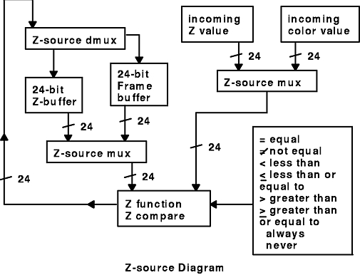
The zsource subroutine selects either depth or color as the source for z comparisons. After a call to the gbegin, ginit, greset, or winopen subroutine, the default z-buffering is done with depth (z) values.
Note: The zsource subroutine is unavailable on the POWER Gt4 and POWER GXT1000 adapters.
You can set the source for comparison on color buffers rather than on the z-buffer. This is useful primarily for drawing antialiased lines that cross each other. The syntax is as follows:
void zsource(Int32 source)
The figure shows the implementation of the z-source function.
A logical operation determines how the system combines the color for each pixel produced by a primitive with the current color of the destination pixel in the frame buffer.
The logicop subroutine specifies the bit-wise logical operation for writing pixels. The logical operation is applied between the incoming (source) and existing (destination) values to generate the final pixel value. In color map mode, all writemask-enabled index bits (up to 12) are changed. In RGB mode, all enabled component bits (up to 24) are changed.
The logicop subroutine is valid in all drawing modes (NORMALDRAW, UNDERDRAW, OVERDRAW, PUPDRAW, and CURSORDRAW) and in both color map and RGB modes. This subroutine affects all drawing operations, including points, lines, polygons, and pixel area transfers. The setting of the logicop subroutine does NOT apply to pixel block transfers to the z-buffer. The syntax is as follows:
void logicop(Int32 opcode)
You can also read "Configuring the Frame Buffer" and how frame buffer update relates to "Creating Animated Scenes" and "Removing Hidden Surfaces".