This section discusses the basic techniques of lighting, including:
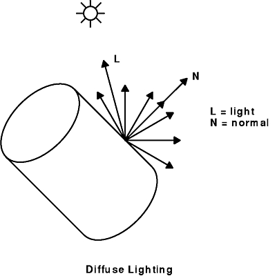
The cylinder1.c example program (found in Symbol.&TRGraphics;) illustrates how to use GL to light a cylinder using a simple lighting calculation. Consider a pale gray cylinder with a rough surface that is illuminated by a source of white light. Objects with rough surfaces tend to reflect or scatter light equally in all directions. Such reflections are termed diffuse reflections.
In our simple lighting calculation, the color and intensity of the diffusely reflected light at a point on the surface depends on three things:
The short arrows in the following figure show how the diffuse light is scattered equally in all directions.
The orientation of the reflecting surface is specified by the surface normal vector, which is perpendicular to the surface at the point in question. The normal vector must be normalized (must be of unit length). Because the surface normal differs at every point on a curved surface, the calculation for reflected light produces a different color at every point on the surface.
The number of points used in the lighting calculations depends on the number of vertices used to define the surface. For a local light (a light not very far from the surface), the system computes a color at every vertex of the polygon mesh used to represent the surface. The application writer must specify the surface-normal vector at every vertex of the polygon mesh.
In addition to the light originating from the light source that reflects off the surface, ambient light is also accounted for in the model. Ambient light is assumed to be nondirectional and is reflected uniformly in all directions by the reflecting surface. Thus, the color and intensity of the reflected ambient light are functions of both the level of ambient light in the scene and the reflectance properties of the surface. They are not functions of the angular relationship between the source of light and the surface normal.
The example C language program cylinder1.c introduces four new subroutines that use the GL lighting facility. The new subroutines are mmode, lmdef, lmbind, and n3f.
To perform lighting calculations, the system must be able to distinguish between the projection matrix (used by the perspective subroutine) and the viewing and modeling matrix (used by the lookat subroutine and the rotate subroutine). The mmode subroutine is used to indicate to the hardware which matrices represent projection transformations and which represent viewing or modeling transformations.
The lmdef subroutine, called from the def_simple_light_calc subroutine of the example program, found in in GL3.2 Version 4 for AIX: Graphics Library (GL) Technical Reference, defines instances of the three necessary components to perform a lighting calculation:
The program line lmdef(DEFMATERIAL, 1, 0, NULL) tells GL about surface material number 1. The value given the first parameter, DEFMATERIAL , indicates that you are defining a surface material. The value for the second parameter defines this material as material number 1 . The value for the third parameter (0 ) is the length of the properties array specified by the fourth parameter. The properties array specifies the properties of the surface material. Here, NULL instructs GL to use the default values for surface materials.
The next two calls to the lmdef subroutine are similar to the first. By substituting DEFMATERIAL with DEFLIGHT, and subsequently DEFLMODEL , you can define a light source and lighting model using the default values prescribed by GL. The default values for a surface material, a light source, and a lighting model are all that are necessary to perform a simple lighting calculation. Properties of a lighting model are the properties that affect the entire scene rather than a specific light source or surface material (the intensity and color of the ambient light in the scene). The subroutine lmdef is covered in greater detail in the section on lighting subroutines.
Another subroutine introduced in the example program is the lmbind subroutine. Once you have defined a surface material, light source, and lighting model you can instruct GL to use them when performing lighting calculations. The three calls to the lmbind subroutine in the example program tell the system to use the material, light source, and light model defined by the lmdef subroutine.
It is more efficient to define surface materials, light sources, and lighting models before activating them with the lmbind subroutine because more computation is involved in defining models than in invoking them. By predefining all the materials, light sources, and lighting models to use in your application, you can quickly switch among different materials and lighting sources when drawing a scene.
There can be only one active light model and surface material at any one time. However, you can use up to the value of MAXLIGHTS lights, where MAXLIGHTS is a constant defined in the /usr/include/gl/gl.h file. (The value is 8 for the High Performance 3-D Color Graphics Processor, and should not be changed.) The example program cylinder2.c (found in in GL3.2 Version 4 for AIX: Graphics Library (GL) Technical Reference) uses multiple lights.
The final new subroutine is the n3f subroutine. Use it to define surface normal vectors. Look at the n3f subroutine called from the draw_cylinder subroutine of the example program (found in in GL3.2 Version 4 for AIX: Graphics Library (GL) Technical Reference) . In the simple lighting calculation, the resultant color at a vertex depends on the angular relationship between the surface normal at that vertex and the light source direction.
The call to the n3f subroutine sends a normal vector of unit length to the graphics hardware to be transformed and subsequently used for a lighting calculation. Each time a different normal is sent to the graphics hardware, a lighting calculation is performed and the resultant color is associated with the vertex (using the v3f subroutine) following the n3f command.
If you have not done so already, try running the example program cylinder1.c. Notice as the cylinder rotates, the color changes to different shades of gray. This is because the angular relationships between the surface normals and the light source (which happens to be located behind our eye along the z axis) is changing.
Also, note that as the interior of the cylinder comes into view, the interior color appears a constant shade of dark gray. This is because the surface normals are facing away from the light source, so the interior of the cylinder is illuminated only by ambient light, which is independent of the direction of the light source.
Now that you have seen how to implement a simple lighting calculation, you can expand the capabilities of the lighting calculation to include specularity and multiple surface materials and lights.
What if the cylinder in the example were made of a shiny metal instead of a rough material? Compared to rough or diffusely reflecting surfaces that reflect light equally in all directions, smooth surfaces tend to reflect light in a directional manner. This directional reflection, called specular reflection, is what causes highlights.
On a perfectly smooth surface such as a mirror, the direction of a reflected ray is equal to the angle of incidence (that is, the angle between the light direction vector and the surface normal vector). On surfaces that are less than perfectly smooth there will be some scattering of the reflected light. Thus, the angle of the reflected light is weighted towards, but not always equal to, the angle of incidence (see the following figure).
Calculations for diffusely reflected light from a light source depend on the angular relationship between the surface normal and light source direction, as well as the reflectance characteristics of the surface. In addition to reflectance characteristics, specularly reflected light depends on the angular relationships between the surface normal, light source direction, and view direction. When the view direction coincides with the direction of the reflected light rays, the viewer sees a specular highlight or glare.
The surface material of the cylinder can be made to appear smoother by incorporating specular reflections. You can do this by changing the def_simple_light_calc subroutine to look like this:
def_simple_light_model(){
   lmdef(DEFMATERIAL, 1, 11, shiny_material);
   lmdef(DEFLIGHT, 1, 0, NULL);
   lmdef(DEFLMODEL, 1, 0, NULL);
}
At the module level of the program, include the definition for the shiny_material property array:
float  shiny_material[] = {
         SPECULAR, 0.8, 0.8, 0.8,
         DIFFUSE, 0.4, 0.4, 0.4,
         SHININESS, 30.0,
         LMNULL};
Now we have provided a non-NULL properties array; values are available for further lighting calculations. Properties are set by specifying a property identifier followed by the expected values for that property. In our example, we set the specular reflectance (using SPECULAR as the property identifier) of the surface for the red, green, and blue components of white light to [0.8 , 0.8 , and 0.8], respectively. Likewise, the diffuse reflectance was set to [0.4 , 0.4 , 0.4] .
Reflectance components vary between 0.0 and 1.0 (0.0 being 0% reflective and 1.0 being 100% reflective). The shininess property indicates how smooth or shiny the surface appears. The higher the number, the smoother the surface, and subsequently the more focused the specular highlight.
The values for SHININESS can range from 0.0 (no specular highlight) to 128.0 (very focused specular highlight). The shininess specified should be a whole number. When a property identifier and the corresponding values are specified in a call to the lmdef subroutine, the new value for that property overrides a default that is provided by GL. This way, you have to specify only those properties whose default values you do not want.
You must always end a property list with the LMNULL token. This token lets GL know that you are finished specifying properties. There are more properties for surface materials that we have not discussed as well as other properties that apply specifically to lighting models and light sources. A complete description of all the properties available to the lmdef subroutine call and their defaults appears in the section on Lighting Subroutines .
If you run the example program with these changes, you will notice how much shinier the cylinder looks. Watch how the highlight appears when the surface normals point at your eye and disappear as they move away.
The next example program displays two intersecting cylinders, using a different surface material for each cylinder. You can also light each cylinder with two light sources. Study the example program cylinder2.c (found in in GL3.2 Version 4 for AIX: Graphics Library (GL) Technical Reference) .
At the top of the program, a second property list is defined for a new material called purple_material and a property list for a second light called blue_light . In the blue_light property list, the light direction is specified as [0.0, 1.0, 0.0, 0.0 ]. The first three numbers specify the xyz direction of the light. The direction vector [0.0, 1.0, 0.0] indicates that the light direction is along the y axis pointing towards the origin.
In other words, the blue light is above the cylinders and pointing toward them. The fourth number (0.0 ) indicates that the light is positioned infinitely far away along the direction vector (in our example the y axis). Differences between infinite and noninfinite lights are discussed in "Advanced Lighting Capabilities".
The LCOLOR specifies the RGB color of the light. This light has only blue color. By varying the values of each of the three color components between 0.0 and 1.0 you can vary the intensity of the light. That is, setting the blue light color to [0.0, 0.0, 0.6] produces a more intense blue than it would have been if you had set the color to [0.0, 0.0, 0.3 ].
In the def_light_calc subroutine, additional material and light source are defined using the lmdef subroutine. In the use_light_calc portion of the program, both light sources are bound because both are used during the entire animation. However, because you want to switch back and forth between surface materials, the program does not bind the surface material until ready to use it. In the main loop, the program performs an
lmbind(MATERIAL, 1)
before drawing the first cylinder and then another
lmbind(MATERIAL, 2)
when drawing the second cylinder.
When you run the example program cylinder2.c, notice that the first cylinder has the same surface material as the cylinder drawn by the example program cylinder1.c, but that the second cylinder consists of a duller, purple material. In addition, each cylinder reflects different amounts of the blue overhead light.