The GL lighting facility is implemented with seven additional subroutines to the Graphics Library:
All lighting model property names and constants are symbolically defined in the /usr/include/gl/gl.h file.
The n3f subroutine takes the address of an array of three floating-point numbers (the vector parameter) and sets the value for the current vertex normal. Normal vectors are assumed to be of unit length, therefore, the equation
should equal 1.0. The normal vector is transformed into eye coordinates using the inverse transpose of the current viewing matrix. It is then stored for use by the lighting equation.
New normals can occur as frequently as every new graphics position and as infrequently as desired. If only one normal is given per polygon and the lighting equation is evaluated on a per-normal basis (when using an infinite viewer and infinite light sources), then the calculations are done only once per polygon. The syntax is as follows:
void n3f(Float32 vector[3])
The normal subroutine takes exactly the same parameter as the n3f subroutine. The only difference is that normal can be used in display lists and n3f cannot. The syntax is as follows:
void normal(Coord narray[3])
The mmode subroutine takes one integer parameter (mode), which is either MSINGLE, MPROJECTION, or MVIEWING. The different modes are necessary to maintain a separate projection matrix and a separate modeling/viewing matrix and its inverse transpose.
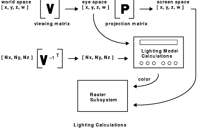
The modeling/viewing matrix transforms model coordinates into eye coordinates where the lighting calculations are performed. The inverse transpose of this matrix is used to transform normals from model coordinates into eye coordinates. The projection matrix transforms eye coordinates into screen coordinates. The figure entitled Lighting Calculations shows how the various matrices operate on display list coordinates and normal vectors to produce screen coordinates and colors.
The lighting equation uses output of the modeling/viewing matrix and its inverse transpose. To use the lighting facility, it is necessary to call mmode(MVIEWING) before setting viewing or modeling matrices. This informs the system that future transformation subroutines will affect the modeling/viewing matrix and its inverse transpose. Each of the matrix modes is described fully in the following sections. The syntax is as follows:
void mmode(Int16 mode)
MSINGLE mode is the default mode. The viewing, modeling, and projection matrices are combined into one matrix, which the getmatrix subroutine returns. Because all matrices are combined in MSINGLE mode, there is no way to transform model coordinates into eye coordinates or to transform normals. Therefore, the lighting model facility does not work in MSINGLE mode. Entering or exiting from MSINGLE mode pops the entire matrix stack and leaves the current matrix undefined.
In MPROJECTION mode, all matrix subroutines deal only with the projection matrix. There is only one projection matrix, and the pushmatrix and popmatrix subroutines result in errors in MPROJECTION mode. The getmatrix subroutine returns the current projection matrix. The modeling/viewing matrix is disabled while in MPROJECTION mode: the results of transforming points in MPROJECTION are undefined.
In MVIEWING mode, all matrix subroutines deal only with the modeling/viewing matrix and its inverse transpose. All matrix subroutines premultiply or load the modeling/viewing matrix by the matrix, and premultiply or load the inverse transpose viewing matrix with the inverse transpose of the matrix.
For the loadmatrix and multmatrix subroutines, the matrix has to be inverted, so singular matrices will cause an error. In MVIEWING mode, the getmatrix subroutine returns the modeling/viewing matrix. The perspective, window, ortho, and ortho2 subroutines load a projection matrix even in MVIEWING mode. Because these subroutines do not affect the modeling/viewing matrix stack and because it is common to build a viewing matrix using subroutines that only multiply matrices, it normally is necessary to load an identity matrix onto the modeling/viewing matrix stack before defining the viewing matrix.
The getmmode subroutine returns the current matrix mode. The values returned can be compared to the values of MSINGLE, MPROJECTION, and MVIEWING to determine the current mode. Mode identifiers are defined in the /usr/include/gl/gl.hfile. The syntax is as follows:
Int32 getmmode()
The lmdef subroutine defines a new material, light source, or lighting model and takes four parameters. The first parameter, deftype, specifies what is to be defined and is either DEFMATERIAL , DEFLIGHT , or DEFLMODEL . The second parameter, index, is the name or index into the table of stored materials, light sources, or lighting models. Indexes for each of these groups are independent. You can define up to 65535 materials, 65535 light sources, and 65535 lighting models. However, index 0 is predefined for each group and cannot be changed.
The third parameter, numpoints, is the length of the properties array and is the number of floating point numbers contained within the array. The fourth parameter, properties, is the properties array, which is a list of properties to be assigned to the material, light source, or lighting model. Values in the array are property identifiers, each followed by the appropriate number of data values. All identifiers and data values are floating-point numbers. Only property identifiers appropriate for the object being defined should be included in the properties array. The last entry must be LMNULL (0.0) . Property identifiers are defined in the /usr/include/gl/gl.h file.
All properties have default values that have been chosen for their efficient execution. The first time a material, light, or lighting property is defined, it is initialized to the default values. A definition can be set to all default values by calling the lmdef subroutine with either a null pointer to the property array (C programming language only) or with LMNULL (0.0) as the first and only property identifier.
Incremental changes can be made to a material, light source, or lighting model definition. Each call to the lmdef subroutine changes only the properties included in its properties array. Properties that are not specified in the properties array keep their previous values. Any valid property can be changed regardless of whether that property is relevant to the current lighting calculation. However, changes made to a definition that is currently bound are effective immediately.
The format of the properties array is a sequence of property identifiers each followed by the appropriate number of data values. The last array entry must be LMNULL. Described below are the material, light source, and lighting model properties along with the number of data values that follow each identifier. Each property is called by its symbolic name. The syntax is as follows:
void lmdef(Int16 deftype, Int32 index,
           Int16 numpoints, Float32 properties[])
Material properties are all the properties a material groups together to define its surface characteristics, such as diffuse reflectance and shininess. The available material properties are as follows:
The default values for material properties are:
| EMISSION | 0.0, 0.0, 0.0 |
| AMBIENT | 0.2, 0.2, 0.2 |
| DIFFUSE | 0.8, 0.8, 0.8 |
| SPECULAR | 0.0, 0.0, 0.0 |
| SHININESS | 0.0 |
| ALPHA | 1.0 |
| COLORINDEXES | 0.0, 127.5, 255.0 |
Light source properties are all the properties a light source groups together to define its characteristics, such as color and position. The available light properties are as follows:
The default values for light source properties are:
| AMBIENT | 0.0, 0.0, 0.0 |
| LCOLOR | 1.0, 1.0, 1.0 |
| POSITION | 0.0, 0.0, 1.0, 0.0 |
| SPOTDIRECTION | 0.0, 0.0, -1.0 |
| SPOTLIGHT | 0.0, 180.0 |
Lighting model properties are all the properties of a lighting model, such as scene ambient light and distance attenuation factors. The available lighting model properties are as follows:
The default values for lighting models are:
| AMBIENT | 0.2, 0.2, 0.2
|
The lmbind subroutine takes two integer parameters: the first, target, specifies the target of the bind and the second, index, is the index of the source. When a source is bound to a target, it becomes current and subsequent evaluations of the lighting equation use its values. The syntax is as follows:
void lmbind(Int16 target, Int32 index)
The three types of targets are as follows:
| MATERIAL | If the target of a bind is MATERIAL, the source material becomes the
currently bound material. There is only one material target and therefore
only one currently bound material.
Source materials are specified using the same index as when the material was defined using the lmdef subroutine. For example, lmbind (MATERIAL, 2) binds material definition 2 to the currently bound material. Material 0 is the default material and disables lighting calculations. This is the most efficient method to disable the lighting calculations. It is functionally equivalent to binding lighting model 0. If an undefined material is the source for the lmbind subroutine, material 0 is bound instead. |
| LIGHTS | There are MAXLIGHTS lights available as targets (LIGHT0, LIGHT1, and
so on), and therefore a MAXLIGHTS number of current lights. If the target
of a bind is a light, then the source light replaces whatever light was
previously bound to the target. The replaced light is turned off and the
newly bound light is turned on. To turn a light off, bind light index 0
to the target light.
Source lights are specified using the same index as when the light was defined using the lmdef subroutine. For example, lmbind (LIGHT3, 54) binds user light definition 54 to system light 3. Light index 0 is the default light and while bound disables lighting calculations for the system light target. If an undefined light is the source to the lmbind subroutine, light 0 is bound instead. When a local light is bound, its position is transformed by the current modeling/viewing matrix and stored. If the light is infinite, its position is taken as its direction and is also transformed by the current modeling/viewing matrix and stored. Thus, by binding a light after some modeling transformations, a light can easily be made part of an object that is moved through the scene (for example, a handheld candle). |
| LMODEL | If the target of a bind is LMODEL, then the source lighting model becomes
the current lighting model. There is only one lighting model target and
therefore only one current lighting model.
Source lighting models are specified using the same index as when the lighting model was defined using the lmdef subroutine. For example, lmbind (LMODEL, 1) binds lighting model 1 to the current lighting model. Lighting model 0 is the default lighting model and disables all lighting calculations. If an undefined lighting model is the source for the lmbind subroutine, lighting model 0 is bound instead. |
The discussion of the lmcolor subroutine appears in "Advanced Lighting Capabilities".