Once all three layers are active, the DTE can set up calls and transfer data to other DTEs. To do this, the X.25 protocol uses different types of packets to make or accept the call, transfer data, and end calls. The X.25 communications software performs most of the tasks involved in creating the packets. You do not need to know the contents of each packet, you need only supply the information necessary to create it.
The way calls work on SVCs is different from the way calls work on PVCs. SVCs are more commonly used, and they initiate the DTE to DTE connection with a call-request packet.
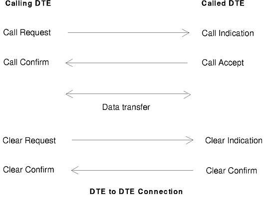
The DTE to DTE connection shown in the figure illustrates how a call is set up, used, and cleared. The call uses a virtual circuit for the duration of the call. This circuit can be reused once the call is over.
Data sent during the call is divided up into units. The size of these units is the packet size. Packet size applies to the size of each data packet, not all packets. The default packet size is 128 bytes. When one unit of data needs to be sent that is greater than the packet size, a number of packets are sent. This sequence of packets is marked to indicate that it makes up one unit of data through use of a flag called the more or M bit. The packet size can be varied from 128 either through configuration or at call setup time. Allowing more data in each packet can have performance gains as there is a degree of overhead for every packet sent. The packet size is one of the call's characteristics that can be changed at call setup. Requests to make changes at this time are controlled by facility requests.
Usually the calling DTE is responsible for inserting all the facility requests it needs. Sometimes though, the network inserts the facility requests into the call packet to indicate to the remote DTE certain characteristics of the local DTE, one of which can be packet size. The contents of a packet, when it reaches the called DTE, may be different from the packet that left the calling DTE. Packet contents may change because some information differs for each DTE (for example, logical channel numbers) or only applies to one of the DTEs. The name given to a packet also varies to indicate if it is received or sent.
Packets are grouped into the following categories, according to type:
The call-setup packets contain different types of information:
A facility is a service provided by the X.25 network. Some facilities are offered as options by the network provider. Negotiating packet size, for example, is a standard facility on most networks, while reverse-charging acceptance is optional. Some optional facilities, such as reverse-charging acceptance, are valid for all virtual calls. Other facilities, such as reverse charging, must be specifically requested for the duration of a call. Certain facilities can be allowed or disallowed for a given X.25 port. If not disallowed, the requested facilities can be used during call setup.
The X.25 facilities and their coding are defined in the CCITT Recommendation X.25, Sections 6 and 7. The facilities you can use are defined in your X.25 subscription.
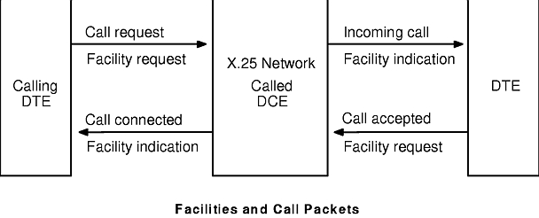
To use a valid facility during a virtual call, a facility request and the facility's corresponding parameters must be inserted in the call packet. The X.25 program on the data terminal equipment (DTE) can insert a facility request in the call request (calling DTE) or in the call accepted (called DTE) packet. Coding of the facilities is the responsibility of the X.25 application and not of the application programming interface (API), device driver, or X.25 microcode.
The network DCE can also notify the DTE of the use and parameters of a facility. The DCE inserts a facility indication, either in the incoming-call packet or in the call-connected packet. The Facilities and Call Packets figure illustrates the call-packet names.
The following table lists the main facilities that may be requested by the DTE or the DCE for the duration of a call.
| X.25 Optional Facilities | |||
| Facilities | 1980 | Request | Indicator |
| Throughput class selection | yes | yes | yes |
| Flow-control parameters selection | yes | yes | yes |
| CUG selection | * | yes | |
| Reverse charging | yes | yes | yes |
| Fast select | yes | yes | yes |
| Recognized private operating agency (RPOA) selection | yes | yes | |
| Network user identification (NUI) | yes | ||
| Call redirection notification | yes | ||
| Charging requesting service | yes | ||
| Note: *Basic CUG only in CCITT 1980. | |||
The Throughput Class Selection facility allows you to change your default throughput class (measuring the transmission speed within the network) to a lower value. This action does not affect the DTE-to-DCE speed, only the speed at which a packet traverses the switching nodes in the network.
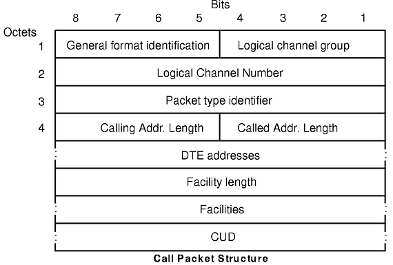
The Call Packet Structure figure shows the structure of a call packet. Call requests, incoming calls, call-accepted packets, and call-connected packets all have the same structure.
Facility requests or facility indications are inserted between the address block and the call user data (CUD) and are prefixed by an octet containing the total length of the facilities. For information on coding and decoding facilities, see "Supported Facilities for X.25 Communications".
Your application is responsible for coding a facility you want to use and inserting it in the call-request or call-accepted packet. The xtalk command , Transmission Control Protocol/Internet Protocol (TCP/IP) , and System Network Architecture (SNA) Services allow the user optionally to define a facility request to be inserted in the call packet.