Several models have been used to specify how networks work. One of the most common of these conceptual models is the International Standards Organization's Open System Interconnect (OSI) Reference Model , also referred to as the OSI 7-layer model . The OSI model numbers the seven layers, or levels, beginning at the lowest (physical) level, as follows:
| 7 | Application |
| 6 | Presentation |
| 5 | Session |
| 4 | Transport |
| 3 | Network |
| 2 | Data Link |
| 1 | Physical |
Levels 1-3 are network-specific, and differ depending on the physical network used. Levels 4-7 are network-independent, higher-level functions. The X.25 protocol has three levels . These levels correspond to Levels 1, 2, and 3 of the OSI model as follows:
| Physical level | OSI Level 1 (Physical) |
| Link level/Frame Level | OSI Level 2 (Data Link) |
| Packet level | OSI Level 3 (Network) |
The X.25 protocol can be quite complicated to set up. If protocol information is required, refer to a communications textbook. Each layer relies on the lower layers to be functional for it to work. If a problem is encountered when setting up an X.25 connection, each layer should be checked to see if it is active.
The physical level activates, maintains, and deactivates the physical circuit between a DTE and a DCE. The physical level is implemented as a STREAMS driver and performs the following functions:
This implementation supports three physical interfaces: V.24, V.35, and X.21bis. CCITT recommendations V.24 and V.35 are found in 1988 volume VIII.I. The CCITT X.21bis is found in volume VIII.
The packet layer produces X.25 packets to establish calls and transfer data. All these packets are then passed to the frame layer for transmission to the local DCE. The frame layer uses a link-access procedure to ensure that data and control information are accurately exchanged over the physical circuit between the DTE and DCE. It provides recovery procedures and is based on a subset of the high-level data-link control (HDLC) protocol called LAP-B . It is synchronous and full-duplex. Once a link is started, either station can transfer information without waiting for permission from the other.
In HDLC all commands, responses, and data are transmitted in frames. Each frame has a header containing address and control information, and a trailer containing a frame-check sequence. Normally, none of this is seen when using X.25.
The three types of frames are:
The packet-level protocol specifies how X.25 controls calls and data transfers between systems. There are many networks running X.25, and a number of these are interconnected. Each system connected to the network has an address to identify it, and this address is used when a connection from the local system to the remote is being requested.
When a system is installed with X.25 and a network subscription obtained, various pieces of configuration information are supplied by the network provider. This information is used to configure the X.25 software. One or more X.25 lines can be connected and for each line, an X.25 port will be configured.
The data transfer capacity of the X.25 line may be shared between a number of different sessions. The maximum number of subscriptions is based on the network subscription and the capabilities of the DTE hardware and software. Each session is called a virtual circuit. A virtual circuit is a data circuit between the local and remote systems, but a circuit that may have its route switched within the network. The element of the network subscription that limits the number of simultaneous virtual circuits in use is the number of logical channels subscribed to. Each virtual circuit takes up a logical channel for the period the circuit is active.
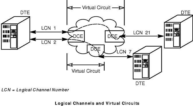
Logical channels are the communications paths between a DTE and its data circuit-terminating equipment (DCE). For 15 simultaneous connections across a network, the network supplier must provide 15 logical channels. Valid logical channel numbers range from 1 to 4095 (logical channel number 0 is usually reserved for diagnostics). The network provider assigns the specific logical channel numbers, and each number must match between the DTE and its DCE. For example, a DTE configured to use logical channels 51-58 could not communicate with its DCE using logical channels 3002-3009. However, when a DTE communicates with another DTE across a packet-switched data network (PSDN), the DTE logical channel numbers do not have to match. The logical channel is not end-to-end in the network; it must only match between each DTE/DCE pair, as shown in the Logical Channels and Virtual Circuits figure.
When a user application begins a session with another DTE on the network, a virtual circuit is established from one DTE to the other, through the DCEs on the network. For an outgoing call, the system that originates the call automatically selects a free channel. When an incoming call is received, the system's local DCE selects the channel. Each application running between two hosts requires use of a virtual circuit. There are two kinds of virtual circuits, permanent (PVC) and switched (SVC), of which SVCs are the more commonly used. Normally when using an SVC, it is not necessary to know the logical channel number in use; the X.25 software ensures that the data from a given session goes over the appropriate virtual circuit. It is necessary to know the logical channel number a given session is on when using PVCs or when tracing the traffic on the X.25 line.
Some applications multiplex their own connections over one virtual circuit. For example, in AIX, once a virtual circuit is established between two machines for TCP/IP , all TCP/IP traffic between those machines flows on that circuit.
It is important that the virtual circuit ranges used for configuration agree with those defined by the network provider.
Configure permanent virtual circuits (PVCs) to agree with the network provider's subscription. The subscription is permanently configured so that the PVC occupying a particular local communications network (LCN) connects to a remote machine on a specified LCN on the remote machine. This allows call setup time to be saved, but dedicates the channel to that one remote system. This makes PVCs less flexible and less likely to be used.
A switched virtual circuit (SVC) is a virtual circuit that exists only for the duration of the call, acting like a connection over a telephone network. There are three types of logical channels for SVCs:
| Incoming | The DTE can only receive calls on this channel. |
| Outgoing | The DTE can only initiate calls on this channel. |
| Two-Way | The DTE can both receive and initiate calls on this channel. |
These channel types are significant only during call initiation. Once a virtual circuit has been established, it is always for two-way communication. Typically, only two-way SVCs are used. However, if more than one type is used, the CCITT states that the logical channel numbers must be assigned within the following hierarchy, from the lowest logical channel numbers to the highest:
If a system has only two-way SVCs, then it is possible that at any given time they could all be in use by incoming calls. If the ability to make an outgoing call must to be guaranteed, then an outgoing-only SVC would perform that function.
Each system on an X.25 network has an address to identify it. This address is supplied by the network provider. To ensure that the address is unique across different network providers and between different countries, the X.121 specification defines an international numbering scheme that ensures a unique DTE address. This address is called the network user address (NUA) . For communication between systems, it is the remote system's NUA that must be known.
Most public networks use the X.121 addressing standard (defined in CCITT Volume VIII.3) to create NUAs. Under the X.121 addressing standard, an NUA consists of the following parts:
A data network identification code (DNIC) consists of 4 digits that include:
Note: Because of the limitation of 1 digit to define only 10 PDNs within one single country, the United States obtained CCITT permission to use 1 digit for the DCC and 2 digits to specify a PDN.
Following the DNIC are 10 digits assigned by the PDN. No rule determines how the national terminal numbers (NTNs) are made up. Most PDNs reserve the last 2 digits as an optional subaddress for the X.25 subscriber. It is the NTN, when communication is made within a given network, that is often given as the system's NUA. The optional subaddress is not processed by the PDN, but is available to identify a finer granularity of address on the remote system. The DNIC is usually used when the remote system is on a different network from the calling system.
The following shows the structure of the network user address (NUA), leaving two digits for the subaddress.
Data Network Identification   National Terminal Number   Optional Subaddress
           1234                      56789012                    34
The X.121 addressing standard also defines a 1-digit optional prefix for international calls. If a call is beyond PDN boundaries, the user or application establishing the call can add a 0 or a 1 at the beginning of the NUA. If a call is within PDN boundaries, no prefix is necessary. The maximum length of an NUA is 15 digits.