The optimal settings of the tunable communications parameters vary with the type of LAN as well as with the communications-I/O characteristics of the predominant system and application programs. The following sections describe the global principles of communications tuning, followed by specific recommendations for the different types of LAN.
You can choose to tune primarily either for maximum throughput or for minimum memory use. Some recommendations apply to one or the other; some apply to both.
If the application were using TCP, this would waste time as well as memory. TCP tries to form outbound data into MTU-sized packets. If the MTU of the LAN were larger than 14976 bytes, TCP would put the sending thread to sleep when the tcp_sendspace limit was reached. It would take a timeout ACK from the receiver to force the data to be written.
Note: When the no command is used to change parameters, the change is in effect only until the next system boot. At that point all parameters are initially reset to their defaults. To make the change permanent, you should put the appropriate no command in the /etc/rc.net file.
Most communication drivers provide a set of tunable parameters to control transmit and receive resources. These typically control the transmit queue and receive queue limits. These parameters limit the number of buffers or packets that may be queued for transmit or limit the number of receive buffers that are available for receiving packets. These parameters can be tuned to ensure enough queueing at the adapter level to handle the peak loads generated by the system or the network.
For transmit, the device drivers may provide a transmit queue limit. There may be both hardware queue and software queue limits, depending on the driver and adapter. Some drivers have only a hardware queue, some have both hardware and software queues. Some drivers internally control the hardware queue and only allow the software queue limits to be modified. Generally, the device driver will queue a transmit packet directly to the adapter hardware queue. If the system CPU is fast relative to the speed of the network, or on a SMP system, the system may produce transmit packets faster than they can be transmitted on the network. This will cause the hardware queue to fill. Once the hardware queue is full, some drivers provide a software queue and will then queue to the software queue. If the software transmit queue limit is reached, then the transmit packets are discarded. This can affect performance because the upper level protocols must then timeout and retransmit the packet.
Prior to AIX release 4.2.1, the upper limits on the transmit queues were in the range of 150 to 250, depending on the specific adapter. The system default values were quite low, typically 30. With AIX release 4.2.1 and later, the transmit queue limits were increased on most of the device drivers to 2048 buffers. The default values were also increased to 512 for most of these drivers. The default values were increased because of the faster CPUs and SMP systems can overrun the smaller queue limits.
For adapters that provide hardware queue limits, changing these values will cause more real memory to be consumed because of the associated control blocks and buffers associated with them. Therefore. these limits should only be raised if needed or for larger systems where the increase in memory use is negligible. For the software transmit queue limits, increasing these does not increase memory usage. It only allows packets to be queued that were already allocated by the higher layer protocols.
Some adapters allow you to configure the number of resources used for receiving packets from the network. This might include the number of receive buffers (and even their size) or may simply be a receive queue parameter (which indirectly controls the number of receive buffers). The receive resources may need to be increased to handle peak bursts on the network.
There several status utilities that can be used. For AIX 4.1.0 and later, the adapter statistics show the transmit queue high water limits and number of queue overflows. You can use netstat -v , or go directly to the adapter statistics utilities (entstat for Ethernet, tokstat for Token Ring, fddistat for FDDI, atmstat for ATM, etc.)
For example, entstat -d en0 output is below. This shows the statistics from en0 . The -d options will list any extended statistics for this adapter and should be used to ensure all statistics are displayed.
Note: These values may represent the hardware queue if the adapter does not support a software transmit queue. If there are Transmit Queue Overflows, then the hardware or software queue limits for the driver should be increased.
If there are not enough receive resources, this would be indicated by Packets Dropped: and depending on the adapter type, would be indicated by Out of Rcv Buffers or No Resource Errors: or some similar counter.
ETHERNET STATISTICS (en1) :
Device Type: IBM 10/100 Mbps Ethernet PCI Adapter (23100020)
Hardware Address: 00:20:35:b5:02:4f
Elapsed Time: 0 days 0 hours 7 minutes 22 seconds

Transmit Statistics:                          Receive Statistics:
--------------------                          -------------------
Packets: 1869143                              Packets: 1299293
Bytes: 2309523868                             Bytes: 643101124
Interrupts: 0                                 Interrupts: 823040
Transmit Errors: 0                            Receive Errors: 0
Packets Dropped: 0                            Packets Dropped: 0
                                              Bad Packets: 0
Max Packets on S/W Transmit Queue: 41
S/W Transmit Queue Overflow: 0
Current S/W+H/W Transmit Queue Length: 1

Broadcast Packets: 1                          Broadcast Packets: 0
Multicast Packets: 0                          Multicast Packets: 0
No Carrier Sense: 0                           CRC Errors: 0
DMA Underrun: 0                               DMA Overrun: 0
Lost CTS Errors: 0                            Alignment Errors: 0
Max Collision Errors: 0                       No Resource Errors: 0
Late Collision Errors: 0                      Receive Collision Errors: 0
Deferred: 3778                                Packet Too Short Errors: 0
SQE Test: 0                                   Packet Too Long Errors: 0
Timeout Errors: 0                             Packets Discarded by Adapter: 0
Single Collision Count: 96588                 Receiver Start Count: 0
Multiple Collision Count: 56661
Current HW Transmit Queue Length: 1

General Statistics:
-------------------
No mbuf Errors: 0
Adapter Reset Count: 0
Driver Flags: Up Broadcast Running
        Simplex 64BitSupport
Another method is to use the netstat -i utility. If it shows non-zero counts in the Oerrs column for an interface, then typically this is the result of output queue overflows. This works for all versions of AIX.
You can use the list attributes command lsattr -E -l [ adapter-name] or you can use SMIT to show the adapter configuration.
Different adapters have different names for these variables. For example, the transmit queue parameter may be named sw_txq_size, tx_que_size, or xmt_que_size. The receive queue size and or receive buffer pool parameters may be named rec_que_size, rx_que_size, or rv_buf4k_min, for example.
Below is the output of a lsattr -E -l atm0 command on a IBM PCI 155 Mbs ATM adapter. This shows the sw_txq_size is set to 250 and the rv_buf4K_min receive buffers set to x30 .
==== lsattr -E ========
dma_mem        0x400000    N/A                                          False
regmem         0x1ff88000  Bus Memory address of Adapter Registers      False
virtmem        0x1ff90000  Bus Memory address of Adapter Virtual Memory False
busintr        3           Bus Interrupt Level                          False
intr_priority  3           Interrupt Priority                           False
use_alt_addr   no          Enable ALTERNATE ATM MAC address             True
alt_addr       0x0           ALTERNATE ATM MAC address (12 hex digits)  True
sw_txq_size    250         Software Transmit Queue size                 True
max_vc         1024        Maximum Number of VCs Needed                 True
min_vc         32          Minimum Guaranteed VCs Supported             True
rv_buf4k_min   0x30        Minimum 4K-byte pre-mapped receive buffers   True
interface_type 0           Sonet or SDH interface                       True
adapter_clock  1           Provide SONET Clock                          True
uni_vers       auto_detect N/A                                          True
Here is an example of a Microchannel 10/100 Ethernet settings using the lsattr -E -l ent0 command. This shows the tx_que_size and rx_que_size both set to 256 .
bus_intr_lvl  11              Bus interrupt level                False
intr_priority 3               Interrupt priority                 False
dma_bus_mem   0x7a0000        Address of bus memory used for DMA False
bus_io_addr   0x2000          Bus I/O address                    False
dma_lvl       7               DMA arbitration level              False
tx_que_size   256             TRANSMIT queue size                True
rx_que_size   256             RECEIVE queue size                 True
use_alt_addr  no              Enable ALTERNATE ETHERNET address  True
alt_addr      0x              ALTERNATE ETHERNET address         True
media_speed   100_Full_Duplex Media Speed                        True
ip_gap        96              Inter-Packet Gap                   True
The easiest way is to detach the interface (ifconfig en0 detach , for example) and then use SMIT -> devices -> communications -> [adapter type] -> change/show... to show the adapter settings.
After you show the settings, move the cursor to the field you would like to change and press F4 to see the minimum and maximum range for the field or the specific set of sizes supported. You can select one of these sizes and then press Enter to enter the request and update the ODM database. Bring the adapter back on line (ifconfig en0 [hostname] , for example).
The other method to change these parameters is to use the chdev command:
chdev -l [ifname] -a [attribute-name]=newvalue
For example, to change the above tx_que_size on en0 down to 128 use the following sequence of commands. Note that this driver only supports four different sizes, so it is better to use SMIT to see these values.
     ifconfig en0 detach
     chdev -l ent0 -a tx_que_size=128
     ifconfig en0 [hostname] up
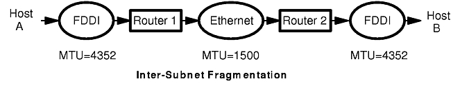
The TCP protocol includes a mechanism for both ends of a connection to negotiate the maximum segment size (MSS) to be used over the connection. Each end uses the OPTIONS field in the TCP header to advertise a proposed MSS. The MSS that is chosen is the smaller of the values provided by the two ends.
The purpose of this negotiation is to avoid the delays and throughput reductions caused by fragmentation of the packets when they pass through routers or gateways and reassembly at the destination host.
The value of MSS advertised by the TCP software during connection setup depends on whether the other end is a local system on the same physical network (that is, the systems have the same network number) or whether it is on a different, remote, network.
If the other end is local, the MSS advertised by TCP is based on the MTU (maximum transfer unit) of the local network interface:
TCP MSS = MTU - TCP header size - IP header size.
Since this is the largest possible MSS that can be accommodated without IP fragmentation, this value is inherently optimal, so no MSS tuning is required for local networks.
When the other end is on a remote network, TCP in AIX defaults to advertising an MSS of 512 bytes. This conservative value is based on a requirement that all IP routers support an MTU of at least 576 bytes.
The optimal MSS for remote networks is based on the smallest MTU of the intervening networks in the route between source and destination. In general, this is a dynamic quantity and could only be ascertained by some form of path MTU discovery. The TCP protocol does not provide any mechanism for doing this, which is why a conservative value is the default.
While this default is appropriate in the general Internet, it can be unnecessarily restrictive for private internets within an administrative domain. In such an environment, MTU sizes of the component physical networks are known and the minimum MTU and optimal MSS can be determined by the administrator. AIX provides several ways in which TCP can be persuaded to use this optimal MSS. Both source and destination hosts must support these features. In a heterogeneous, multi-vendor environment, the availability of the feature on both systems may determine the choice of solution.
The default MSS of 512 can be overridden by specifying a static route to a specific remote network and using the -mtu option of the route command to specify the MTU to that network. In this case, you would specify the actual minimum MTU of the route, rather than calculating an MSS value.
In a small, stable environment, this method allows precise control of MSS on a network-by-network basis. The disadvantages of this approach are:
The default value of 512 that TCP uses for remote networks can be changed via the no command by changing the tcp_mssdflt parameter. This change is a systemwide change.
The value specified to override the MSS default should be the minimum MTU value less 40 to allow for the normal length of the TCP and IP headers.
In an environment with a larger-than-default MTU, this method has the advantage that the MSS does not need to be set on a per-network basis. The disadvantages are:
Several physical networks can be made to share the same network number by subnetting (see "TCP/IP Addressing"). The no option subnetsarelocal specifies, on a system-wide basis, whether subnets are to be considered local or remote networks. With subnetsarelocal=1 (the default), Host A on subnet 1 considers Host B on subnet 2 to be on the same physical network.
The consequence of this is that when Host A and Host B establish a connection, they negotiate the MSS assuming they are on the same network. Each host advertises an MSS based on the MTU of its network interface. This usually leads to an optimal MSS being chosen.
This approach has several advantages:
At the IP layer, the only tunable parameter is ipqmaxlen, which controls the length of the IP input queue discussed earlier (which exists only in AIX Version 3). Packets may arrive very quickly and overrun the IP input queue. In the AIX operating system, there is no simple way to determine if this is happening. However an overflow counter can be viewed using the crash command. To check this value, start the crash command and when the prompt appears, type knlist ipintrq . This command returns a hexadecimal value, which may vary from system to system. Next, add 10 (hex) to this value, and then use it as an argument for the od subcommand. For example:
# crash
> knlist ipintrq
 ipintrq: 0x0149ba68
> od 0149ba78 1
0149ba78: 00000000 <--    This is the value of the IP input queue
                          overflow counter
>quit
If the number returned is greater than 0, overflows have occurred. The maximum length of this queue is set using the no command. For example:
no -o ipqmaxlen=100
allows 100 packets to be queued up. The exact value to use is determined by the maximum burst rate received. If this cannot be determined, using the number of overflows can help determine what the increase should be. No additional memory is used by increasing the queue length. However, an increase may result in more time spent in the off-level interrupt handler, since IP will have more packets to process on its input queue. This could adversely affect processes needing CPU time. The tradeoff is reduced packet dropping versus CPU availability for other processing. It is best to increase ipqmaxlen by moderate increments if the tradeoff is a concern.
Ethernet is one of the contributors to the "least common denominator" algorithm of MTU choice. If a configuration includes Ethernets and other LANs, and there is extensive traffic among them, the MTUs of all of the LANs may need to be set to 1500 bytes to avoid fragmentation when data enters an Ethernet.
The default MTU of 1492 bytes is appropriate for Token Rings that interconnect to Ethernets or to heterogeneous networks in which the minimum MTU is not known.
The default MTU of 1492 bytes is appropriate for Token Rings that interconnect to Ethernets or to heterogeneous networks in which the minimum MTU is not known.
Despite the comparatively low MTU, this high-speed medium benefits from substantial increases in socket buffer size.