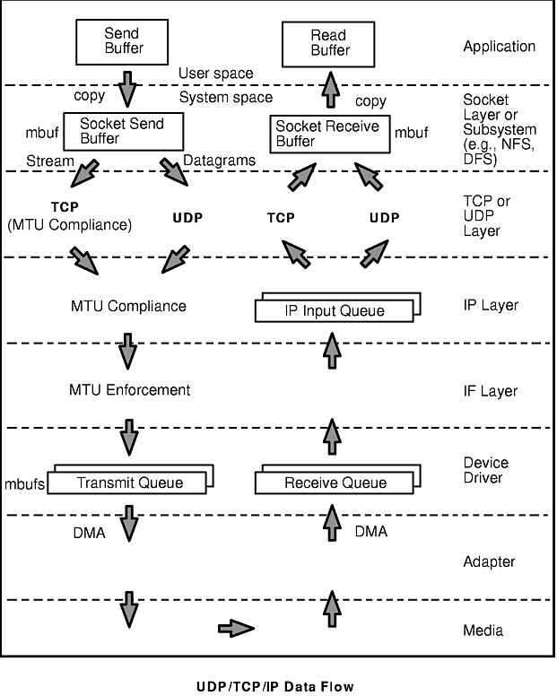
To understand the performance characteristics of UDP and TCP/IP, you must first understand some of the underlying architecture. The "UDP/TCP/IP Data Flow" figure illustrates the structure that will be discussed in this chapter.
The figure shows the path of data from an application in one system to another application in a remote system. The processing at each of the layers will be discussed in detail later, but briefly (ignoring error handling and buffer limits):
To avoid fragmentation of kernel memory and the overhead of numerous calls to xmalloc(), common buffer pools are shared by the various layers of the communication subsystem. The mbuf management facility controls two pools of buffers: a pool of small buffers (256 bytes each), which are simply called mbufs, and a pool of large buffers (4096 bytes each), which are usually called mbuf clusters or just clusters. These pools are usually referred to collectively as "mbufs." The pools consist of pinned pieces of kernel virtual memory; this means that they always reside in physical memory and are never paged out. The result is that the real memory available for paging in application programs and data has been decreased by the amount that the mbuf pools have been increased.
In addition to avoiding duplication, sharing the mbuf and cluster pools allows the various layers to pass pointers to one another, reducing mbuf management calls and copying of data.
Sockets provide the application program interface (API) to the communication subsystem. There are several types of sockets that provide various levels of service by using different communication protocols. Sockets of type SOCK_DGRAM use the UDP protocol. Sockets of type SOCK_STREAM use the TCP protocol.
The semantics of opening, reading, and writing to sockets are similar to those for manipulating files.
The sizes of the buffers in system virtual memory (that is, the total number of bytes from the mbuf pools) that are used by the input and output sides of each socket are limited by system-wide default values (which can be overridden for a given socket by a call to the setsockopt() subroutine):
These values can be displayed with
$ no -a
and set (by root ) with, for example:
# no -o udp_sendspace=NewValue
The NewValue parameter must be less than or equal to the sb_max parameter, which controls the maximum amount of space that can be used by a socket's send or receive buffer. sb_max is displayed with no -a and set (before attempting to exceed its current value) with the no command:
# no -o sb_max=NewLimit
Note: Socket send or receive buffer sizes are limited to no more than sb_max bytes, because sb_max is a ceiling on buffer space consumption. The two quantities are not measured in the same way, however. The socket buffer size limits the amount of data that can be held in the socket buffers. sb_max limits the number of bytes of mbufs that can be in the socket buffer at any given time. In an Ethernet environment, for example, each 4096-byte mbuf cluster might hold just 1500 bytes of data. In that case, sb_max would have to be 2.73 times larger than the specified socket buffer size to allow the buffer to reach its specified capacity. Our rule of thumb is that sb_max should be set to at least twice the size of the largest socket buffer.
As an application writes to a socket, the data is copied from user space into the socket send buffer in kernel space. Depending on the amount of data being copied into the socket send buffer, the socket puts the data into either mbufs or clusters. Once the data is copied into the socket send buffer, the socket layer calls the transport layer (either TCP or UDP), passing it a pointer to the linked list of mbufs (an mbuf chain).
On the receive side, an application opens a socket and attempts to read data from it. If there is no data in the socket receive buffer, the socket layer causes the application thread to go to the sleep state (blocking) until data arrives. When data arrives, it is put on the receive socket buffer queue and the application thread is made dispatchable. The data is then copied into the application's buffer in user space, the mbuf chain is freed, and control is returned to the application.
In AIX Version 4.3.1 and later, the sockthresh value determines how much of the system's network memory can be used before socket creation is disallowed. The value of sockthresh is given as a percentage of thewall. It has a default of 85% and can be set to any value from 1 to 100. However, sockthresh cannot be set to a value lower than the amount of memory currently in use.
The sockthresh option is intended to prevent the case where many connections are opened until all the network memory on the machine is used. This leaves no memory for other operations, and the machine hangs and must be rebooted to recover. Use sockthresh to set the point at which new sockets should not be allowed. Calls to socket() and socketpair() will fail with an error of ENOBUFS, and incoming connection requests will be silently discarded. This allows the remaining network memory to be used by existing connections and prevents the machine from hanging.
The netstat -m statistic sockets not created because sockthresh was reached is incremented each time a socket creation fails because the amount of network memory already in use is over the sockthresh.
sockthresh can be displayed with
$ no -o sockthresh
and set (by root) with
# no -o sockthresh=NewValue
sockthresh can be set to its default value with
# no -d sockthresh
The following two sections contain descriptions of the function of UDP and TCP. To facilitate comparison of UDP and TCP, both descriptions are divided into subsections on: connection, error detection, error recovery, flow control, data size, and MTU handling.
UDP provides a low-cost protocol for applications that have the facilities to deal with communication failures. UDP is most suitable for "request-response" applications. Since such an application has to handle a failure to respond anyway, it is little additional effort to handle communication error as one of the causes of failure to respond. For this reason, and because of its low overhead, subsystems such as NFS, ONC RPC, DCE RPC, and DFS use UDP.
| Connection | None. UDP is essentially a stateless protocol. Each request received from the caller is handled independent of those that precede or follow it. (If the connect() subroutine is called for a datagram socket, the information about the destination is considered a hint to cache the resolved address for future use. It does not actually bind the socket to that address or affect UDP on the receiving system.) |
| Error detection | Checksum creation and verification. The sending UDP builds the checksum and the receiving UDP checks it. If the check fails, the packet is dropped. |
| Error recovery | None. UDP does not acknowledge receipt of packets, nor does it detect their loss in transmission or through buffer-pool overflow. Consequently, UDP never retransmits a packet. Recovery must be performed by the application. |
| Flow control | None. When UDP is asked to send, it sends the packet to IP. When a packet arrives from IP, it is placed in the socket-receive buffer. If either the device driver/adapter buffer queue or the socket-receive buffer is full when the packet arrives there, the packet is dropped without an error indication. The application or subsystem that sent the packet must detect the failure by timeout and retry the transmission. |
| Data size | Must fit in one buffer. This means that the buffer pools on both sides of UDP must have buffer sizes that are adequate for the applications' requirements. The maximum size of a UDP packet is 64KB. Of course, an application that builds large blocks can break them into multiple datagrams itself--DCE is an example--but it is simpler to use TCP. |
| MTU handling | None. Dealing with data larger than the maximum transfer unit (MTU) size for the interface is left to IP. If IP has to fragment the data to make it fit the MTU, loss of one of the fragments becomes an error that the application or subsystem must deal with. |
If udp_sendspace is large enough to hold the datagram, the application's data is copied into mbufs in kernel memory. If the datagram is larger than udp_sendspace, an error is returned to the application.
If the datagram is larger than or equal to 936 bytes, it is copied into one or more 4KB clusters. The remainder (and any complete datagram) of less than 936 bytes is copied into 1-4 mbufs. For example, a write of 8704 bytes is copied into two clusters and the remainder into three mbufs. UDP adds the UDP header (in the same mbuf, if possible), checksums the data, and calls the IP ip_output routine.
UDP verifies the checksum and queues the data onto the proper socket. If the udp_recvspace limit is exceeded, the packet is discarded. (A count of these discards is reported by netstat -s under "udp: " as "socket buffer overflows .") If the application is waiting on a receive or read on the socket, it is put on the run queue. This causes the receive to copy the datagram into the user's address space and release the mbufs, and the receive is complete. Normally, the receiver will respond to the sender to acknowledge the receipt and also return a response message.
TCP provides a reliable-transmission protocol. TCP is most suitable for applications that, at least for periods of time, are mostly output or mostly input. With TCP ensuring that packets reach their destination, the application is freed from error detection and recovery responsibilities. Applications that use TCP transport include ftp, rcp, and telnet. DCE can use TCP if it is configured to use a connection-oriented protocol.
| Connection | Explicit. The instance of TCP that receives the connection request from an application (we will call it the initiator) establishes a session with its counterpart on the other system, which we will call the listener. All exchanges of data and control packets are within the context of that session. |
| Error detection | Checksum creation and verification. The sending TCP builds the checksum and the receiving TCP checks it. If checksum verification fails, the receiver does not acknowledge receipt of the packet. |
| Error recovery | Full. TCP detects checksum failures and loss of a packet or fragment through timeout. In error situations TCP retransmits the data until it is received correctly (or notifies the application of an unrecoverable error). |
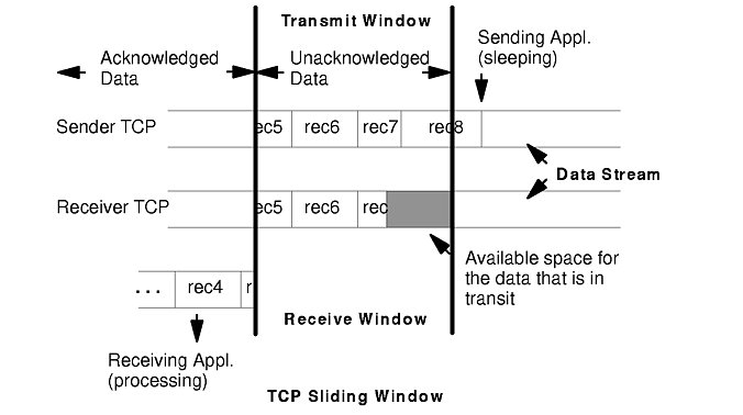
| Flow control | Enforced. TCP uses a discipline called a sliding window to ensure delivery to the receiving application. The sliding window concept is illustrated in the figure "TCP Sliding Window."
(The records shown in the figure are for clarity only. TCP processes data as a stream of bytes and does not keep track of record boundaries, which are application-defined.)
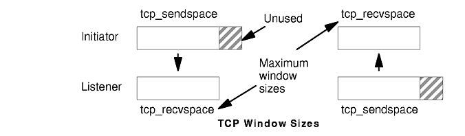
In the figure, the sending application is sleeping because it has attempted to write data that would cause TCP to exceed the send socket buffer space (i.e., tcp_sendspace). The sending TCP still has the last part of rec5, all of rec6 and rec7, and the beginning of rec8. The receiving TCP has not yet received the last part of rec7 or any of rec8. The receiving application got rec4 and the beginning of rec5 when it last read the socket, and it is now processing that data. When the receiving application next reads the socket, it will receive (assuming a large enough read), the rest of rec5, rec6, and as much of rec7 and rec8 as has arrived by that time. Once the next read occurs, the receiving TCP will be able to acknowledge that data, the sending TCP will be able to discard the data, the pending write will complete, and the sending application will wake up. (To avoid excessive LAN traffic when the application is reading in tiny amounts, TCP delays acknowledgement until the receiving application has read a total amount of data that is at least half the receive window size or twice the maximum segment size.) In the course of establishing a session, the initiator and the listener converse to determine their respective capacities for buffering input and output data. The smaller of the two sizes defines the size of the window. As data is written to the socket, it is moved into the sender's buffer. When the receiver indicates that it has space available, the sender transmits enough data to fill that space (assuming that it has that much data). When the receiving application reads from the socket, the receiving TCP returns as much data as it has in its buffer. It then informs the sender that the data has been successfully delivered. Only then does the sender discard the data from its own buffer, effectively moving the window to the right by the amount of data delivered. If the window is full because the receiving application has fallen behind, the sending thread will be blocked (or receive a specific errno) when it tries to write to the socket. The figure"TCP Window Sizes" shows the relationship between the socket buffer sizes and the window size. tcp_recvspace in both of these systems is smaller than tcp_sendspace to illustrate a point: since the moving-window technique requires that the two systems be able to buffer the same amount of data, the window size is set to the lesser value in both directions. The nominally available extra space for buffering output shown in the figure is never used. If the rfc1323 parameter is 1, the maximum TCP window size is 4GB (instead of 64KB). |
| Data size | Indefinite. TCP does not process records or blocks, it processes a stream of bytes. If a send buffer is larger than the receiver can handle, it is segmented into MTU-size packets. Because it handles shortages of buffer space under the covers, TCP does not guarantee that the number and size of data receives will be the same as the number and size of sends. It is the responsibility of the two sides of the application to identify record or block boundaries, if any, within the stream of data.
Note: When using TCP to exchange request/response messages, the application must use setsockopt to turn on the TCP_NODELAY option. This causes TCP to send the message immediately (within the constraints of the sliding window), even though it is less than MTU-size. Otherwise, TCP would wait for up to 200 milliseconds for more data to send before transmitting the message. The consequences for performance are obvious. |
| MTU handling | Handled by segmentation in TCP. When the connection is established, the initiator and the listener negotiate a maximum segment size (MSS) to be used. The MSS is normally smaller than the MTU (see "Tuning TCP Maximum Segment Size (MSS)"). If the output packet size exceeds the MSS, TCP does the segmentation, thus making fragmentation in IP unnecessary. The receiving TCP normally puts the segments on the socket receive queue as they arrive. If the receiving TCP detects the loss of a segment, it withholds acknowledgement and holds back the succeeding segments until the missing segment has been received successfully. |
There is, of course, no such thing as free function. The additional operations performed by TCP to ensure a reliable connection result in about 7 to 12% higher processor cost than in UDP.
When the TCP layer receives a write request from the socket layer, it allocates a new mbuf for its header information and copies the data in the socket-send buffer either into the TCP-header mbuf, if there is room, or into a newly allocated mbuf chain. If the data being copied is in clusters, the data is not actually copied into new clusters. Instead, a pointer field in the new mbuf header (this header is part of the mbuf structure and is unrelated to the TCP header) is set to point to the clusters containing the data, thereby avoiding the overhead of one or more 4KB copies. TCP then checksums the data, updates its various state variables, which are used for flow control and other services, and finally calls the IP layer with the header mbuf now linked to the new mbuf chain.
When the TCP input routine receives input data from IP, it checksums the TCP header and data for corruption detection, determines which connection this data is for, removes its header information, links the mbuf chain onto the socket-receive buffer associated with this connection, and uses a socket service to wake up the application (if it is sleeping as described earlier).
The Internet Protocol provides a basic datagram service to the higher layers. If it is given a packet larger than the MTU of the interface, it fragments the packet and sends the fragments to the receiving system, which reassembles them into the original packet. If one of the fragments is lost in transmission, the incomplete packet is ultimately discarded by the receiver. The length of time IP waits for a missing fragment is controlled by the ipfragttl parameter, which is set and displayed with no.
The maximum size of IP's queue of packets received from the network interface is controlled by the ipqmaxlen parameter, which is set and displayed with no. If the size of the input queue reaches this number, subsequent packets are dropped.
When the IP output routine receives a packet from UDP or TCP, it identifies the interface to which the mbuf chain should be sent, updates and checksums the IP part of the header, and passes the packet to the interface (IF) layer.
IP determines the proper device driver and adapter to use, based on the network number. The driver interface table defines the maximum MTU for this network. If the datagram is less than the MTU size, IP adds the IP header in the existing mbuf, checksums the IP header and calls the driver to send the frame. If the driver send queue is full, an EAGAIN error is returned to IP which simply returns it to UDP which returns it to the sending application. The sender should delay and try again.
If the datagram is larger than the MTU size (which only happens in UDP) IP fragments the datagram into MTU-size fragments, appends a IP header (in an mbuf) to each, and calls the driver once for each fragment frame. If the driver's send queue is full, an EAGAIN error is returned to IP. IP discards all remaining unsent fragments associated with this datagram and returns EAGAIN to UDP. UDP returns EAGAIN the sending application. Since IP and UDP do not queue messages, it is up to the application to delay and try the send again.
In AIX Version 3, when the IP input routine receives control as the result of an IF-scheduled off-level interrupt, it dequeues the mbuf chain, checks the IP header checksum to make sure the header was not corrupted, and determines if the packet is for this system. If so, and the frame is not a fragment, IP passes the mbuf chain to the TCP or UDP input routine.
In AIX Version 4, the demux layer (called the IF layer in Version 3) calls IP on the interrupt thread. There is no longer any scheduling or queuing/dequeuing activity. IP checks the IP header checksum to make sure the header was not corrupted and determines if the packet is for this system. If so, and the frame is not a fragment, IP passes the mbuf chain to the TCP or UDP input routine.
If the received frame is a fragment of a larger datagram (which only happens in UDP), IP holds onto the frame. When the other fragments arrive, they are merged into a logical datagram and given to UDP when the datagram is complete. IP holds the fragments of an incomplete datagram until the ipfragttl time (as specified by no) expires. The default ipfragttl time is 30 seconds (an ipfragttl value of 60). If any fragments are lost due to problems such as network errors, lack of mbufs, or transmit queue overruns, IP never receives them. When ipfragttl expires, IP discards the fragments it did receive. This is reported by netstat -s under "ip: " as "fragments dropped after timeout ."
When the IF layer receives a packet from IP, it attaches the link-layer header information to the beginning of the packet, checks the format of the mbufs to make sure they conform to the device driver's input specifications, and then calls the device driver write routine.
In AIX Version 3, when the IF layer receives a packet from the device driver, it removes the link header and enqueues the mbuf chain (done with pointers, not copying) on the IP input queue and schedules an off-level interrupt to do the IP input processing.
In AIX Version 4, when the demux layer receives a packet from the device driver, it calls IP on the interrupt thread to perform IP input processing.
Many different kinds of LAN adapters are supported in the AIX environment. These adapters differ, not only in the communications protocol and transmission medium they support, but also in their interface to the the I/O bus and the processor. Similarly, the device drivers vary in the technique used to convey the data between memory and the adapter. The following high-level description applies to most adapters and device drivers, but details vary.
At the device-driver layer, the mbuf chain containing the packet is enqueued on the transmit queue. The maximum total number of output buffers that can be queued is controlled by the system parameter xmt_que_size. In some cases, the data is copied into driver-owned DMA buffers. The adapter is then signaled to start DMA operations.
At this point, control returns back up the path to the TCP or UDP output routine, which continues sending as long as it has more to send. When all data has been sent, control returns to the application, which then runs asynchronously while the adapter transmits data. When the adapter has completed transmission, it interrupts the system, and the device interrupt routines are called to adjust the transmit queues and free the mbufs that held the transmitted data.
When frames are received by an adapter, they are transferred from the adapter into a driver-managed receive queue. The receive queue may consist of mbufs or the device driver may manage a separate pool of buffers for the device; in either case, the data is in an mbuf chain when it is passed from the device driver to the IF layer.
Some drivers receive frames via DMA into a pinned area of memory and then allocate mbufs and copy the data into them. Drivers/adapters that receive large-MTU frames may have the frames DMA'd directly into cluster mbufs. The driver hands off the frame to the proper network protocol (IP in this example) by calling a demultiplexing function that identifies the packet type and puts the mbuf containing the buffer on the input queue for that network protocol. If no mbufs are available or if the higher-level input queue is full, the incoming frames are discarded.