The family of asynchronous adapters is based on a common functional design. The individual adapter characteristics, however, are determined by the supported device interfaces. The family consists of three adapters:
The family of 8-port adapters is based on the dual universal asynchronous receiver and transmitter (DUART) chip providing two serial communications channels.
The following sections contain detailed information about 8-port adapters:
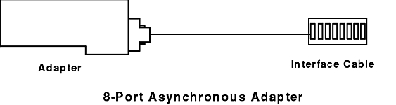
The 8-Port asynchronous adapter, EIA 232, (see figure) provides support for attaching a maximum of eight EIA 232D asynchronous serial devices (such as modems, terminals, plotters, and printers) to a system unit. The system must be based on a Micro Channel bus or an ISA bus and support up to eight 8-port adapters.
This adapter is fully programmable and supports asynchronous communications only. It can also add and remove start and stop bits and supports even, odd, or no parity on serial data. A programmable baud rate generator allows operation from 50 to 38,400 bps for the Micro Channel bus and 50 to 115,200 bps for the ISA bus. The adapters support 5-, 6-, 7-, or 8-bit characters with 1, 1.5, or 2 stop bits. A priority interrupt system controls transmit, receive, error, line status, and data set interrupts.
The 8-port asynchronous adapter fits into a single Micro Channel slot in AIX. To install the adapter use the following steps:
shutdown -F
The system will recognize and configure the 8-port adapter during the boot process.
lsdev -Cc adapter | pg
Only those adapters that are in an available state are ready for use by the system.
If the newly installed adapter is not available, then verify:
If running cfgmgr fails, a reboot will be necessary.
The system interface presents a 3-bit address and 8-bit data as well as control lines to the DUART chip. Data from the system interface is serialized for transmission to an external device. The serial data can include a parity bit at the byte boundary. Conversely, data from an external device is deserialized for transmission to the system interface. This data may also include a parity bit, which can be optionally checked. As an option, the channel can operate in first-in-first-out (FIFO) mode.
In FIFO mode, up to 16 bytes can be buffered in both the transmitter and receiver. The serial interface uses start-stop protocol for both data transmission and reception. That is, each byte (plus the parity bit) is framed by one or more start bits and stop bits, which allows synchronization on an individual character (byte) basis.
The DUART chip uses a 12.288 MHz oscillator to generate its internal timing to drive the transmitter and receiver logic. The channel supports full duplex operation. Four DUART chips are implemented on each 8-port adapter.
Thirteen system-accessible registers are available. Programmable features on each channel include:
The following table is a summary of port (device interface) characteristics for the adapters.
| Parameter | EIA 232 | MIL-STD 188 | EIA 422A |
| Topology | Point to Point | Point to Point | Point to Point |
| Maximum data rate | 138.4Kbps (MC)/115.2 (ISA) | 138.4Kbps | 138.4Kbps |
| Transmission media | Multiconductor | Multiconductor | Multiconductor |
| Number of cable wires | 9 including signal ground | 9 including signal ground | 5 including signal ground |
| Maximum cable length | 61 m (200 feet) | 130 m at 38.4Kbps | 1200 m < 90Kbps |
| Device connector | 25-pin D | 25-pin D | 25-pin D |
| Electrical interface | Unbalanced | Unbalanced | Balanced |
| Bit encoding | Digital bi-level | Digital bi-level | Digital bi-level |
The interrupt arbitration logic sets priority for adapters according to the following scheme:
Adapter   Priority
    1     Highest
    2       |
    3       |
    4       |
    5       |
    6       |
    7       |
    8     Lowest
The DUART channels with pending interrupts are serviced according to a fixed-priority scheme. The highest priority is assigned to port 0. Next in priority is port 1, and so forth. The lowest priority is port 7.
The interrupt logic is divided into two sections:
Both logic sections are implemented on every 8-port adapter. The interrupt generation logic provides the interface to the system. This logic generates the system interrupt requests and contains the interrupt-sharing circuitry.
The function of the interrupt arbitration logic is to identify the 8-port adapter with the highest priority interrupt pending. The logic then places the interrupt information for the highest priority port in the Interrupt Arbitration register. This is accomplished in one read operation.
The interrupt arbitration logic is unique to the 8-port adapter and should not be confused with the Micro Channel arbitration logic.
The adapter implements the following eight system interrupt request lines:
Only one request line is active during normal operation. All 8-port adapters in one system should use the same interrupt level for optimal system performance. The active line is selected by writing to the appropriate POS register during the setup cycle. The adapter supports interrupt sharing and implements an open collector configuration. In this arrangement, the interrupt line is pulled high by a system pull-up resistor. The adapter pulls the line low to indicate an active interrupt request.
Up to eight 8-port adapters can co-reside and concurrently operate in a system. The interrupt arbitration logic determines the priority for software service when two or more 8-port or 16-port adapters generate interrupts. This logic provides the system with adapter and port identification as well as the interrupt type in a single read operation. Once an interrupt request is detected, the system reads the 16-bit interrupt arbitration register, which is located at I/O address 0130.
The following interface signals are implemented on each port of the adapter:
Voltage levels for the MIL-STD 188 Adapter are explained in the following sections:
The signal is in the mark state when the voltage on the interchange circuit, measured at the interface point, is less than -4 V dc with respect to the signal ground. The signal is in the space state when the voltage is greater than +4 V dc with respect to the signal ground. The region between +4 V dc and -4 V dc is defined as the transition region and is not a valid level. The voltage that is less than -6 V dc or greater than +6 V dc is also not a valid level.
During the transmission of data, the mark state denotes binary 1 and the space state denotes binary 0.
For interface control circuits, the function is "on" when the voltage is greater than +4 V dc with respect to the signal ground and is "off" when the voltage is less than -4 V dc with respect to the signal ground. MIL-STD 188 signal levels are shown in the following table:
| Interchange Voltage | Binary State | Signal Condition | Interface Control Function |
| + Voltage | 0 | Space | On |
| - Voltage | 1 | Mark | Off |
Military standard MIL-STD 188 requires that adapters provide the capability to optionally invert the polarities of the mark and space states of the transmit and receive lines. The capability is provided independently on each port.
The DUART modem control register bit 3 (Out 2) is used for this purpose. When bit 3 is set to a value of 1, the polarities for the mark and space states are set to the normal state. When bit 3 is set to a value of 0, the polarities for the mark and space states are inverted.
The signal is in the space state when the voltage is less than -4 V dc with respect to the signal ground. The signal is in the mark state when the voltage is greater than +4 V dc with respect to the signal ground.
The region between +4 V dc and -4 V dc is defined as the transition region and is not a valid level. The voltage that is less than -6 V dc or greater than +6 V dc is also not a valid level.
The electrical characteristics of the 8-Port asynchronous MIL-STD 188 adapter ports conform to those sections of MIL-STD 188-114 that address an unbalanced voltage interface. The standard is dated March 24, 1976.
The adapter ports meet the functional requirements for asynchronous operation (start-stop protocol) as described in the EIA Standard 232C dated October 1969 and in the EIA Standard 232D dated January 1987.
The following EIA 422A interface signals are implemented on each port of the adapter:
| Signal | Definition |
|---|---|
| TxA | Transmit Data |
| TxB | Transmit Data |
| RxA | Receive Data |
| RxB | Receive Data |
| Sig Gnd | Signal Ground |
The line driver produces a differential voltage in the range of 2 to 6 volts (measured at the generator interface point). The magnitude of the differential voltage at the receiver must be in the range of 200 millivolts to 6 volts (measured at the load interface point).
Measurements are taken at terminal A (positive lead) with respect to terminal B (negative lead). The following table describes the signal states with respect to voltage levels:
| Interchange Voltage | Binary State | Signal Condition |
| + Voltage | 0 | Space |
| - Voltage | 1 | Mark |
The 8-Port asynchronous EIA 422A adapter supports indoor cabling up to 1200 m (4000 ft) in length. Cables of such lengths are susceptible to sudden voltage surges due to induced voltages such as indirect lightning strikes. Secondary surge protection circuitry is implemented on the EIA 422A adapter to protect it from these voltage surges. The surge protection circuitry is implemented on the adapter interface data lines.
Fail-safe circuitry has been added to the input leads of each EIA 422A receiver to prevent fault conditions when the receiver is not connected to a driver (open cable). The fail-safe circuitry sets the receiver to the mark state (binary 1) whenever the receiver is not connected to a driver.
The electrical characteristics of the 8-Port asynchronous EIA 422A adapter ports comply with the EIA Standard 422A dated December 1978.
The following interface signals are implemented on each port of the adapter:
| Signal | Definition |
|---|---|
| TxD | Transmit Data |
| RTS | Request To Send |
| CTS | Clear To Send |
| DSR | Data Set Ready |
| RxD | Receive Data |
| DCD | Data Carrier Detect |
| DTR | Data Terminal Ready |
| RI | Ring Indicator |
| Sig Gnd | Signal Ground |
The signal is in the mark state when the voltage on the interchange circuit, measured at the interface point, is less than -3 V dc with respect to the signal ground. The signal is in the space state when the voltage is greater than +3 V dc with respect to the signal ground. The region between +3 V dc and -3 V dc is defined as the transition region and is not a valid level. Voltage less than -15 V dc or greater than +15 V dc is also not a valid level.
During the transmission of data, the mark state denotes binary state 1 and the space state denotes binary state 0.
For interface control circuits, the function is on when the voltage is greater than +3 V dc with respect to the signal ground and is off when the voltage is less than -3 V dc with respect to the signal ground. See the following table for EIA 232 signal levels:
| Interchange Voltage | Binary State | Signal Condition | Interface Control Function |
| + Voltage | 0 | Space | On |
| - Voltage | 1 | Mark | Off |
The electrical characteristics of the 8-Port asynchronous EIA 232 adapter ports conform to the EIA Standard 232C dated October 1969 and to the EIA Standard 232D dated January 1987.
The adapter ports meet the functional requirements for asynchronous operation (start-stop protocol) as described in the EIA Standard 232C dated October 1969 and in the EIA Standard 232D dated January 1987.
The PAL-based control logic section coordinates the activities of all major adapter functions and is clocked with a 40 MHz square-wave generator. It interfaces with the Micro Channel, and its functions include decoding addresses, checking address parity, responding with the proper I/O control signals, and driving the selected interrupt request (IRQ) line (one of eight IRQ lines).
The control logic interfaces with the other adapter logic blocks and in this capacity provides the control lines to the communication channels (DUART) and the interrupt arbitration logic. The control logic also interfaces with the data bus driver logic and provides control for the direction of data flow and for the selection data bytes, which are placed onto the local bus. It controls the data parity generator, parity checker, and latches.