The 128-port asynchronous adapter subsystem meets the multiuser requirements for workstations in the open system environment. The subsystem can support up to 128 devices and offers higher speeds to the end user. It is an intelligent adapter with the ability to offload line protocol processing from the operating system.
The 128-port product consists of an adapter card, up to eight remote asynchronous node (RAN) units, each supporting 16 devices, for a total of 128 devices per adapter. The 128-port asynchronous adapter card resides in the system unit, and is connected by either EIA 422, direct cabling, EIA 422/EIA 232 synchronous modems, or Data Service Unit/Channel Service Units (DSU/CSUs) to the RAN. The number of 128-port asynchronous adapters that can be installed is dependent on the number of slots available in the system with a hardware limit of seven adapters per bus (an optional I/O bus can provide eight additional slots).
To understand the 128-port asynchronous adapter in more detail, consider:
The 128-port asynchronous adapter is an intelligent dual-channel EIA 422 synchronous board for the AIX system. The 128-port asynchronous adapter features the following main components:
The 128-port remote asynchronous node (RAN) is a complete subsystem and contains the following main components:
The RAN receives data packets from the adapter at data rates of up to 1.2 Mbps, and then distributes the data, as appropriate, to the 16 EIA 232 ports. Data received by the EIA 232 ports is similarly divided into packets and sent back to the adapter over the high-speed synchronous line. The EIA 232 ports operate at data rates of up to 57,600 bps.
For local applications, where the work groups are not located more than 300 m (1000 ft) from the system, RANs can be connected to a 128-port asynchronous adapter through 4- or 8-conductor twisted-pair cable (the 8-conductor cable is recommended). With the 8-conductor cable, data is transferred between RANs and the adapter at rates of up to 1.2 Mbps. With 4-wire cable, the maximum synchronous data rate is 460 Kbps.
For more information concerning cable types, lengths, and baud rates, refer to "128-Port Asynchronous Adapter Cable Specifications and Cabling Scenarios".
The 128-port remote asynchronous node (RAN) is a complete subsystem and contains the following main components:
The RAN receives data packets from the adapter at data rates of up to 2.458 Mbps, and then distributes the data, as appropriate, to the 16 EIA 232 ports. Data received by the EIA 232 ports is similarly divided into packets and sent back to the adapter over the high-speed synchronous line. The EIA 232 ports operate at data rates of up to 230 Kbps.
Adapter configuration software will autodetect and configure RANs of multiple types on a single line. Line speed will be limited to 1.2 Mbps when connected on the same line as the original 128-port asyncronous node EIA 232.
For local applications, where the work groups are not located more than 300 m (1000 ft) from the system, RANs can be connected to a 128-port asynchronous adapter through 4- or 8-conductor twisted-pair cable (the 8-conductor cable is recommended). With the 8-conductor cable, data is transferred between RANs and the adapter at rates of up to 1.2 Mbps. With 4-wire cable, the maximum synchronous data rate is 460 Kbps.
For more information concerning cable types, lengths, and baud rates, refer to "128-Port Asynchronous Adapter Cable Specifications and Cabling Scenarios".
The 128-port remote asynchronous node (RAN) is a complete subsystem and contains the following main components:
The RAN receives data packets from the adapter at data rates of up to 2.458 Mbps, and then distributes the data, as appropriate, to the 16 EIA 422 ports. Data received by the EIA 232 ports is similarly divided into packets and sent back to the adapter over the high-speed synchronous line. The EIA 422 ports operate at data rates of up to 230 Kbps.
Adapter configuration software will autodetect and configure RANs of multiple types on a single line. Line speed will be limited to 1.2 Mbps when connected on the same line as the original 128-port asyncronous node EIA 232.
For local applications, where the work groups are not located more than 300 m (1000 ft) from the system, RANs can be connected to a 128-port asynchronous adapter through 4- or 8-conductor twisted-pair cable (the 8-conductor cable is recommended). With the 8-conductor cable, data is transferred between RANs and the adapter at rates of up to 2.458 Mbps. With 4-wire cable, the maximum synchronous data rate is 460 Kbps.
For more information concerning cable types, lengths, and baud rates, refer to "128-Port Asynchronous Adapter Cable Specifications and Cabling Scenarios".
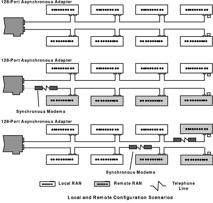
Each 128-port asynchronous adapter has two synchronous lines. Up to four RANs can be connected to a single synchronous line in daisy-chain fashion. That is, the first RAN is connected to one of the adapter's lines, the second RAN is connected to the first RAN, and so on (up to four RANs).
The RANs can be attached to the 128-port adapter with a direct local connection, a synchronous modem connection, or a combination of the two. The following figure shows some of the possible connection types.
Note: Only a single modem connection is allowed per adapter line.
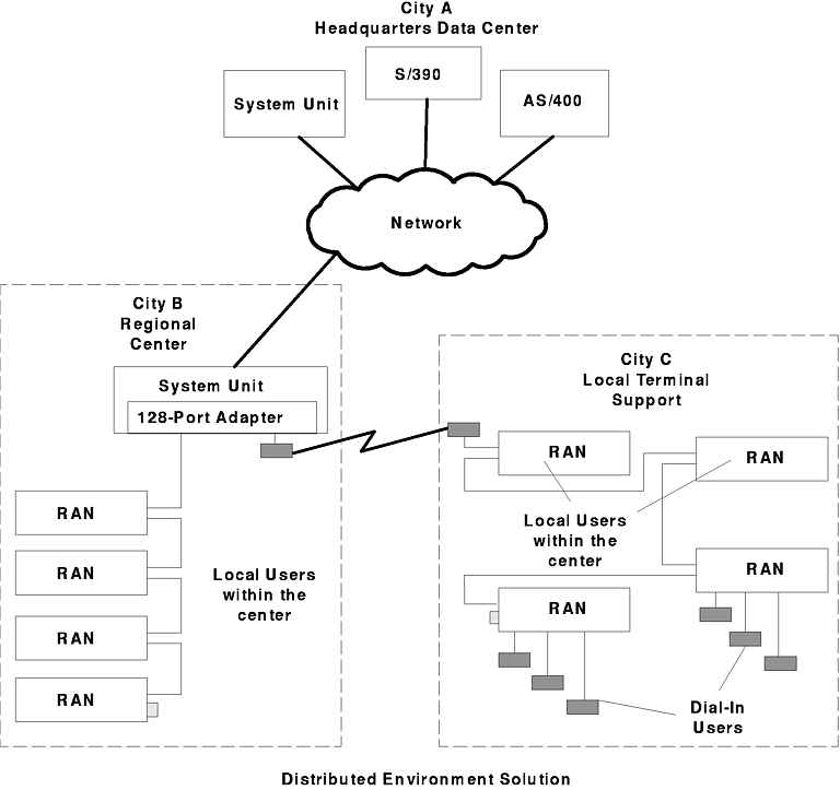
See the following figure for an example of a scenario in a distributed environment using the 128-port asynchronous adapter.
RANs are assigned physical node numbers (set by the operator during installation, see "Setting a RAN Node Number"). The node number is used by the adapter to route data to and from a specific RAN. If a particular RAN is turned off or removed from the daisy chain, the 16 devices on that RAN become unavailable to the system, but the rest of the system remains unaffected. Since the RAN's IN and OUT/T ports are of opposite gender, a direct or local RAN can be removed from the middle of a daisy chain by plugging the cables together so that the chain remains unbroken. To remove the last RAN, simply plug the terminator plug into the end of the daisy-chain cable.
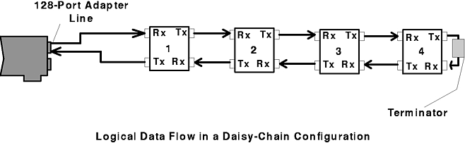
RANs always receive input data via their IN ports and always transmit output data from their OUT/T ports. When multiple RANs are daisy-chained together, data travels in a circular fashion. Thus, if there are four RANs connected to an adapter's synchronous port, data from the adapter to RAN 4 must pass through RAN 1, 2, and 3 before reaching RAN 4. At the same time, data from RAN 1 to the adapter must travel the full circle through RAN 2, 3, and 4 before being returned to the adapter. Refer to the following figure for an example of the data flow.
To make the loop complete, a terminator plug must be installed on the OUT/T port of the last RAN in the daisy chain. This plug ties all of the OUT/T port's output signals back to their corresponding input signals (TxD to RxD, TxC to RxC, and so on). The RAN's OUT/T port input signals are hard-wired to its IN port output signals, so once any RAN's output data reaches the terminator plug on the last RAN, it is passed back through all of the RANs until it is ultimately received by the adapter. Note that if only one RAN is installed, it is by default the last one and needs to have a terminator plug (IBM PN 43G0926) installed.
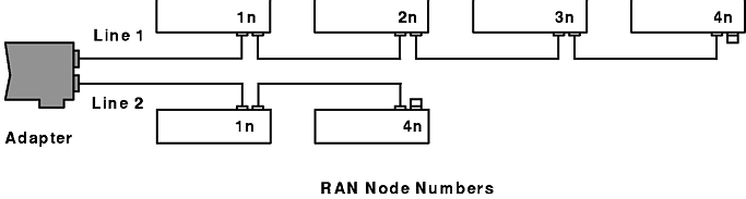
The adapter identifies RANs by their node numbers. Each RAN in a daisy chain must have a unique node number (1n through 4n), which must be set during installation (see " Setting a RAN Node Number"). The node numbers must be assigned in ascending order with the lowest number assigned to the RAN closest to the adapter. You can skip node numbers (to facilitate insertion of additional RANs at a later date), as long as the ascending sequence is maintained. The following figure summarizes the node number assignment.
The number of adapters that can be installed in a system is dependent on the number of available slots. See "Product Selection Considerations" in Chapter 1 for more information.