[ Previous |
Next |
Contents |
Home |
Search ]
AIX Versions 3.2 and 4 Asynchronous Communications Guide
Configuring a RAN with SMIT
The 128-port asynchronous adapter and RAN are automatically configured during the boot process. With locally or directly attached RANs using IBM cabling, it is not necessary to change any of the default parameters supplied by the AIX operating system for the 128-port asynchronous adapter or RAN.
Because the 128-port subsystem is configured during the boot process, administrators should verify that all RANs are correctly set up and cabled before turning on the power of the AIX system. RAN node numbers should be set in an ascending order with the lowest node number being nearest the 128-port asynchronous adapter card.
This section discusses the configuration of the 128-port asynchronous controller for:
Prerequisites
- A 128-port asynchronous adapter must be installed, defined, and available.
- At least one RAN must be connected. See "Connecting a RAN to a 128-Port Asynchronous Adapter".
- Set the RAN's node ID. Refer to "Setting a RAN Node Number.
- Fill out the "128-Port Asynchronous Adapter Planning Worksheets".
Configure a Local or Direct RAN Attachment
- Use the smit ttyadapters fast path to access the 128-Port Async Adapter screen.
- Select the appropriate Micro Channel 128-port adapter (for example, cxma0, cxma1, cxma2), ISA 128-port adapter (for example, cxia0, cxia1, cxia2), or the PCI port adapter cxpa0 to make the change.
- In the displayed dialog fields, supply the values or accept the default values.
- Select Do to implement the new configuration.
Configure a Remote RAN Attachment Using Modem or DSU/CSU
- Use the smit ttyadapters fast path.
- Select the appropriate 128-port asynchronous adapter from the list displayed on the screen.
- To view a list of possible values for each field, move the cursor inside the field and select the List option.
- Change the Comm Mode fields to the appropriate values based on the interface type of your modem or DSU/CSU (data service unit/channel service unit). Refer to "Determining a RAN's Connection Type and SMIT Node Comm Mode Values (AIX Version 4)".
Note: Only one pair of modems or DSU/CSU is allowed per adapter line.
- Select Do to implement the new configuration.
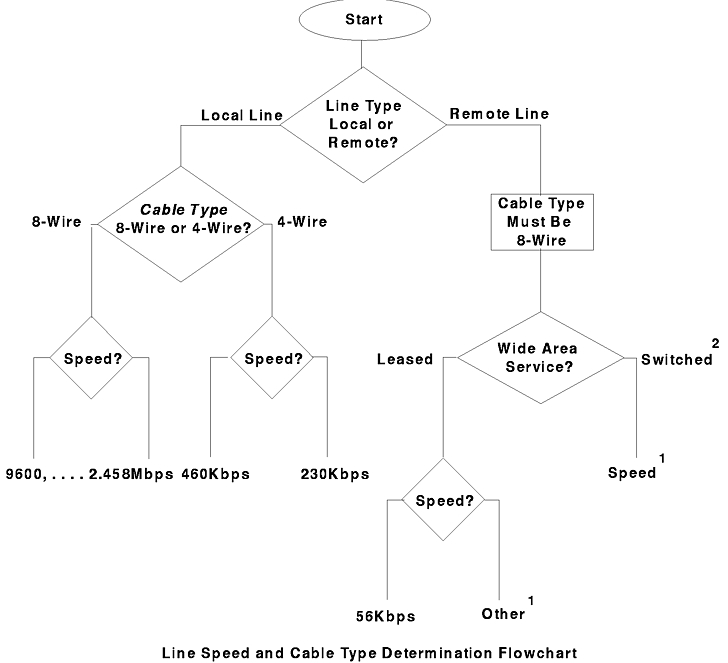
Determining Line Speed and Line Cable Type Values for a RAN
A line from the adapter is considered a remote line whenever there is a modem or DSU/CSU used to connect any pair of RANs within that line. The following flowchart can help you determine the values for the SMIT line speed and cable type parameters.
Notes:
- Set the SMIT line speed parameter based on the line speed provided by the carrier service.
- For initial configuration, the switched line must be manually established and a connection made between the two modems or DSU/CSU in order to bring up the remote RAN.
Determining a RAN's Connection Type and SMIT Node Comm Mode Values (AIX Version 3.2)
For a line that consists of 4 RANs, the value for the Node Comm Mode field is defined as shown in the following table.
| Node Comm Mode Parameter Selection |
| Node Comm Mode |
Description |
| direct |
Selected when no modem is used. |
| 232_modem |
Selected when an EIA 232 modem is used to communicate to the RAN at a remote location. |
| 422_modem |
Selected when an EIA 422 modem is used to communicate to the RAN at a remote location. |
For a line that consists of fewer than 4 RANs, the Node Comm Mode field for a virtual RAN is defined in the following table. A virtual RAN is one that does not physically exist. The sum of the number of physical RANs and virtual RANs is four. For example, if two RANs with node numbers of 1n and 2n are connected to an adapter, 3n and 4n are considered virtual RAN node numbers.
| Node Comm Mode for Virtual RAN |
| Last Physical Ran Node Number |
Virtual RAN Node Number |
Node Comm Mode Value for Virtual Node when the Last Physical RAN is Connected with: |
|
|
EIA 422 Modem |
EIA 232 Modem |
| 1n |
2n 3n 4n |
422_modem direct direct |
232_modem direct direct |
| 2n |
3n 4n |
422_modem direct |
232_modem direct |
| 3n |
4n |
422_modem |
232_modem |
The table can be read as follows:
If the last physical RAN is connected to line 1 (or line 2) and its node number is node 1n, then the virtual RAN node number values are:
- 2n = 422_modem
(or 232_modem
)
- 3n = direct
- 4n = direct
Determining a RAN's Connection Type and SMIT Node Comm Mode Values (AIX Version 4)
For a line that consists of 4 RANs, the value for the Node Comm Mode field is defined as shown in the following table.
| Node Comm Mode Parameter Selection |
| Node Comm Mode |
Description |
| direct |
Selected when no modem is used. |
| none |
Selected when the designated node is not used or does not exist. |
| 232_modem |
Selected when an EIA 232 modem is used to communicate to the RAN at a remote location. |
| 422_modem |
Selected when an EIA 422 modem is used to communicate to the RAN at a remote location. |
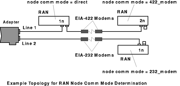
Example Node Comm Mode Parameter Determination
The following two examples summarize the Node Comm Mode field for the virtual nodes.
See the following figure for an example of three RANs. The first is directly connected to the asynchronous adapter line 1; the second is connected to the first with an EIA 422 modem, and the third is connected to the asynchronous adapter line 2 with an EIA 232 modem.
The values of the Node Comm Mode field for this example are:
| Example Node Comm Mode Parameter Determination |
| Line |
Node |
Node Comm Version 3.2 |
Mode Value Version 4 |
| 1 |
1n |
direct |
direct |
|
2n |
422_modem |
422_modem |
|
3n |
422_modem* |
none |
|
4n |
direct* |
none |
| 2 |
1n |
232_modem |
232_modem |
|
2n |
232_modem* |
none |
|
3n |
direct* |
none |
|
4n |
direct* |
none |
| * - Denotes virtual node definition |
Sample 128-Port Asynchronous Adapter Configurations
This section discusses three sample 128-port asynchronous adapter configurations and their corresponding SMIT configurations.
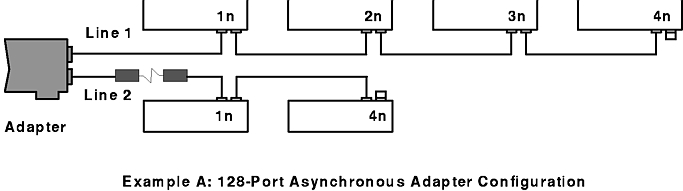
Example A:
Line 1:
- Has four local- or direct-attached RANs with node numbers 1n through 4n.
- Direct attachment at 1.2 Mbps.
Line 2:
- Has no local RANs and two remote RANs with node numbers 1n and 4n.
- Communication is over a leased-line (speed 14.4 Kbps) using EIA 232 synchronous modems.
See the following figure for a diagram of example A.
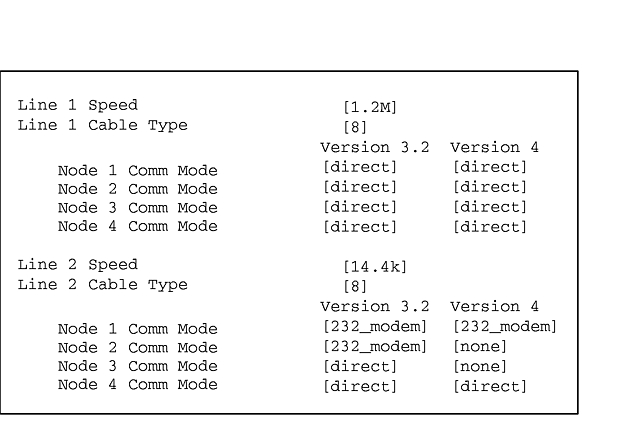
The SMIT fields for the above scenario are shown in the following figure.
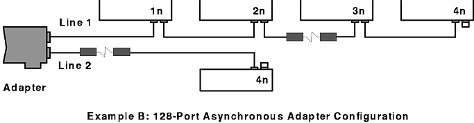
Example B:
Line 1:
- Has two local and two remote RANs
- Local RAN node numbers are 1n and 2n.
- Remote RAN node numbers are 3n and 4n.
- Communication is over a leased-line (speed 56 Kbps) using EIA 232 synchronous modems.
Line 2:
- Has no local RANs and one remote RAN with a node number of 4n.
- Communication is over a leased-line (speed 56 Kbps) using EIA 232 synchronous modems.
See the following figure for a diagram of example B.
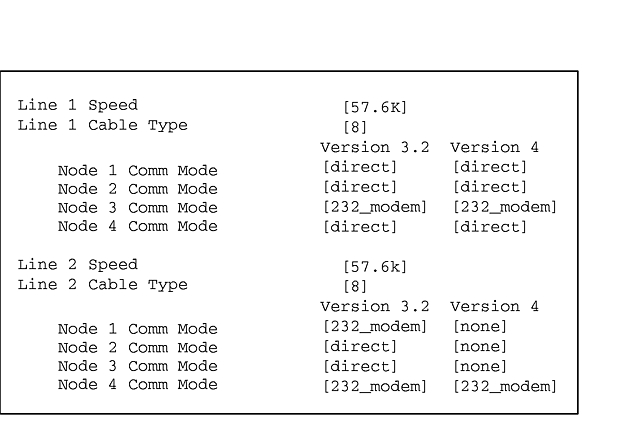
The SMIT fields for the above scenario are shown in the following figure.
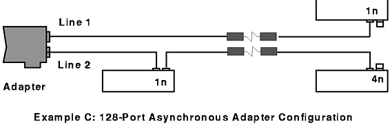
Example C:
Line 1:
- Has no local RANs and one remote RAN with a node number of 1n.
- Communication is over a leased-line (speed 56 Kbps) using EIA 232 synchronous modems.
Line 2:
- Has one local RAN and one remote RAN.
- Local RAN node number is 1n.
- Remote RAN node number is 4n.
- Communication is over a leased-line (speed 56 Kbps) using EIA 232 synchronous modems.
See the following figure for a diagram of example C.
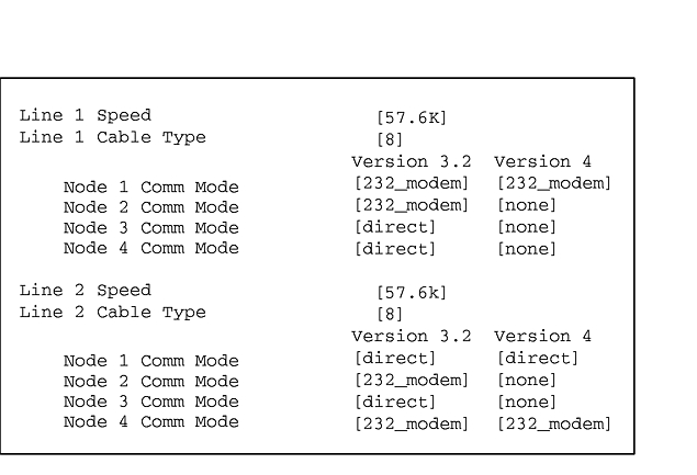
The SMIT fields for the above scenario are shown in the following figure.
Connect Remote RAN to 128-Port Asynchronous Adapter Using Modems
- Connect the local EIA 232 or EIA 422 synchronous modem to one of the adapter synchronous lines using an EIA 232 or EIA 422 synchronous modem cable.
- Connect the remote EIA 232 or EIA 422 synchronous modem to the RAN port marked IN using the EIA 232 or EIA 422 synchronous modem cable. See 128-Port Asynchronous Adapter Cable Specifications and Cabling Scenarios for cable wiring information.
- Install the terminator plug on the OUT/T port of the RAN.
- Plug the AC connector of the power supply (IBM PN 40H3611 for the standard RAN or PN 93H7091 for the enhanced RAN) into a standard grounded wall outlet. Plug the DIN connector into the receptacle labeled +5V/+-12V on the RAN.
- Turn the RAN's power switch to the on position (|). The lights on the front panel should flash as the RAN executes its power-on self-test (POST) sequence. The seven-segment LED display should eventually display P1
to indicate that the POST sequence passed.
- Set the node number. Refer to Setting a RAN Node Number for instructions.
- Reconfigure the adapter by running cfgmgr -l cxia0, cxma0, or cxpa0.
[ Previous |
Next |
Contents |
Home |
Search ]