
| MicroChannel Reference Database |
| Home |
 |
|
The Parallel Port:
Introduction to the IEEE 1284 Standard (1994)
Information and illustrations contained in this page are edited excerpts from the EPRM, Copyright © IBM Corp. 1992-97.
Parallel Port Background
When IBM introduced the PC, in 1981, the parallel printer port was included as an alternative to the slower serial port as a means for driving the latest high performance dot matrix printers. The parallel port had the capability to transfer 8 bits of data at time whereas the serial port transmitted one bit at a time. When the PC was introduced, dot matrix printers were the main peripheral that used the parallel port. As technology progressed and the need for greater external connectivity increased, the parallel port became the means by which you could connect higher performance peripherals. These peripherals now range from printer sharing devices, portable disk drives and tape backup to local area network adapters and CD ROM players.
The problems faced by developers and customers of these peripherals fall into three categories. First, although the performance of the PC has increased dramatically, there has been virtually no change in the parallel port performance or architecture. The maximum data transfer rate achievable with this architecture is around 150 kilobytes per second and is extremely software intensive. Second, there is no standard for the electrical interface. This causes many problems when attempting to guarantee operation across various platforms. Finally, the lack of design standards forced a distance limitation of only 6 feet for external cables.
In 1991 there was a meeting of printer manufactures to start discussions on developing a new standard for the intelligent control of printers over a network. These manufactures, which included Lexmark, IBM, Texas Instruments and others, formed the Network Printing Alliance.
The NPA defined a set of parameters that, when implemented in the printer and host, will allow for the complete control of printer applications and jobs.
While this work was in progress it became apparent that to fully implement this standard would require a high performance bi-directional connection to the PC. The usual means of connection, the ordinary PC parallel port, did not have the capabilities required to meet the full requirements or abilities of this standard.
The NPA submitted a proposal to the IEEE for the creation of a committee to develop a new standard for a high speed bi-directional parallel port for the PC. It was a requirement that this new standard would remain fully compatible with the original parallel port software and peripherals, but would increase the data rate capability to greater than 1M bytes per second, both in and out of the computer. This committee became the IEEE 1284 committee.
The IEEE 1284 standard, "Standard Signaling Method for a Bi-directional Parallel Peripheral Interface for Personal Computers", was approved for final release in March of 1994.
The Parallel Port - An Overview
The parallel port, as implemented on the PC, consists of a connector with 17 signal lines and 8 ground lines. The signal lines are divided into three groups:
As originally designed, the Control lines are used as interface control and handshaking signals from the PC to the printer. The Status lines are used for handshake signals and as status indicators for such things as paper empty, busy indication and interface or peripheral errors. The data lines are used to provide data from the PC to the printer, in that direction only. Later implementations of the parallel port allowed for data to be driven from the peripheral to the PC.
Table 1 identifies each of these signals and gives their Standard Parallel Port (SPP) definitions. The signals within these groups are assigned to specific bits within the registers that make up the hardware/software interface to the parallel port. The parallel port is mapped into the I/O space of the PC. The registers consist as a contiguous block of 3 registers starting from the parallel port's base address. These ports are commonly referred to as the LPT ports and have the familiar I/O base addresses of 3BCh, 378h and 278h. Newer implementations of the parallel port, that support the advanced modes of the 1284 standard, use 8 to 16 registers and are located at I/O addresses 378h or 278h, or are re-locatable, as in the case of a Plug and Play compliant parallel adapter.
Table 1: Standard Parallel Port (SPP) Signal Definitions
| Group | SPP Signal | In/Out | Signal Description |
| Control | nSTROBE | Out | Active low. Indicates valid data is on the data lines. |
| - | nAUTOFEED | Out | Active low. Instructs the printer to automatically insert a line feed for each carriage return. |
| - | nSELECTIN | Out | Active low. Used to indicate to the printer that it is selected. |
| - | Out | nINIT | Active low. Used to reset the printer. |
| Status | nACK | In | A low asserted pulse used to indicate that the last character was received. |
| - | BUSY | In | A high signal asserted by the printer to indicate that it is busy and cannot take data. |
| - | PE | In | Paper Empty |
| - | SELECT | In | Asserted high to indicate that the printer is online. |
| - | nERROR | In | Asserted low to indicate that some error condition exists |
| Data | DATA[8:1] | Out | 8 data lines- output only in older SPP |
Note: The signal usage described in this and all following tables define the usage while in the described data transfer mode. Many of these signals are used for mode transitions and for additional status information. Please refer to the IEEE 1284-1994 standard for the complete definition and usage of these signals. This is meant as an introduction only.
Table 2 identifies the registers for the standard parallel port. The basic method of transferring data to the printer using this port is described in the section Compatibility Mode.
Table 2: SPP Register Definition. Register offset is from the base address of the port.
| Offset | Name | Read/Write | Description |
| 0 | Data Register | R/W | Data port to read or write data |
| 1 | Status Register | R | Contains status bits |
| 2 | Control Register | W | Used to set control signals |
| 3-7 | Various | N/A | Used differently by various implementations |
IEEE 1284 Data Transfer Modes
The use of the various 1284 data transfer modes provide the capability to create a forward and reverse channel connection between the host computer and an attached peripheral. Since there is only one set of data lines the connection is half duplex, data is transferred in one direction at a time.
The Compatibility and Nibble modes of operation can be implemented in any existing parallel port in order to create a complete bi-directional communication path between the host and peripheral. The Compatibility and Byte modes can also be used create a bi-directional communication path, but the the parallel port must support the Byte mode capability. The Byte mode requires that an entire byte of data can be read from the external data lines. This is usually implemented by the addition of a direction bit in the parallel port's Control register. This type of port is generally called a "bi-directional" parallel port.
The EPP and ECP modes have bi-directional capability as part of their protocol. These modes require that the hardware implement a state machine that is capable of automatically generating the control strobes that are necessary for these high performance data transfer modes.
Each of the operating modes, other than Compatibility, rename the control and status signals to have meaning within the mode being used. The discussions for each mode will use the names consistent with the mode being discussed.
Centronics/Compatibility Mode
This mode defines the protocol used by most PCs to transfer data to a printer. It is commonly called the "Centronics" mode and is the method utilized with the standard parallel port. In this mode, data is placed on the port's data lines, the printer status is checked for no errors and that it is not Busy, and then a data Strobe is generated by the software to clock the data to the printer. Figure 1 describes this transfer.
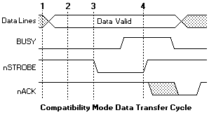
Compatibility Mode phase transitions:
As can be seen, in order to output one byte of data it requires four I/O instructions and at least as many additional instructions. The net effect of this is a limitation on the bandwidth capabilities of the port on the order of 150K bytes per second.
This bandwidth is sufficient for communicating with dot matrix and many older laser printers, but a limitation when communicating with pocket LAN adapters, removable disk drives, and the newest generation of laser printers, to name a few. Of course, this mode is for the forward channel only and must be combined with a reverse channel mode in order to have a complete bi-directional channel.
This mode was included as a way to provide backward compatibility with the huge base of installed printers and peripherals. The other modes are used to provide the reverse channel and high performance communication links.
Many of the integrated 1284 I/O controllers have implemented a mode that uses a FIFO buffer to transfer data with the Compatibility mode protocol. This mode is referred to as "Fast Centronics" or "Parallel Port FIFO Mode". When this mode is enabled, data written to the FIFO port will be transferred to the printer using hardware generated strobes for the handshaking. Since there is very little latency between transfers, and the software does not have to do any of the strobing or handshake checking, data rates over 500K bytes per second are achievable with some systems. This mode, however, is not an IEEE 1284 defined mode and is not described in the standard.
IEEE 1284 Nibble Mode
The Nibble mode is the most common way to get reverse channel data from a printer or peripheral. This mode is usually combined with the Compatibility mode or a proprietary forward channel mode to create a complete bi-directional channel.
All of the standard parallel ports provide 5 lines from the peripheral to the PC to be used for external status indications. Using these lines, a peripheral can send a byte of data (8-bits) by sending 2 nibbles (4-bits) of information to the PC in two data transfer cycles. Unfortunately, since the nACK line is generally used to provide a peripheral interrupt, the bits used to transfer a nibble are not conveniently packed into the byte defined by the Status register. For this reason, the software must read the status byte and then manipulate the bits in order to get a correct byte.
Table 3 identifies the signal names for the Nibble mode. Figure 2 shows the basic data handshake for a nibble mode transfer from the peripheral to the host.
Table 3: Nibble Mode Signals
| SPP Signal | Nibble Mode Name | In/Out | Signal usage when in Nibble Mode data transfer |
| nSTROBE | nSTROBE | Out | Not used for reverse data transfer |
| nAUTOFEED | HostBusy | Out | Host nibble mode handshake signal. Set low to indicate host is ready for nibble. Set high to indicate nibble has been received. |
| nSELECTIN | 1284Active | Out | Set high when host is in a 1284 transfer mode. |
| nINIT | nINIT | Out | Not used for reverse data transfer |
| nACK | PtrClk | In | Set low to indicate valid nibble data. Set high in response to HostBusy going high. |
| BUSY | PtrBusy | In | Used for Data bit 3, then 7 |
| PE | AckDataReq | In | Used for Data bit 2, then 6 |
| SELECT | Xflag | In | Used for Data bit 1, then 5 |
| nERROR | nDataAvail | In | Used for Data bit 0, then 4 |
| DATA[8:1] | Unused | -- | -- |
Figure 2: Basic data handshake for a nibble mode transfer from the peripheral to the host.
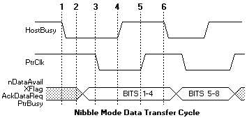
IEEE 1284 Nibble Mode phase transitions
Nibble mode, like the Compatible mode, requires that the software drive the protocol by setting and reading the lines on the parallel port. Nibble mode is the most software intensive mode for reverse channel data communication. For this reason, there is a severe limitation of approximately 50K bytes per second for this type of data transfer. The major advantage of this combination of modes is the ability to operate on all PCs that have a parallel port. The performance limitations incurred by the Nibble mode operation does not have much visible effect on peripherals that have low reverse channel requirements, such as printers, but can be nearly intolerable when used for LAN adapters, disk drives or CD ROM drives.
IEEE 1284 Byte Mode
With later implementations of the parallel port interface, some manufacturers, led by IBM on the PS/2 parallel port, added the capability to disable the drivers used for driving the data lines, and allowed the data port to become an input read data port. This enables a peripheral to send an entire byte of data to the PC in one data transfer cycle by using the 8 data lines, rather than the two cycles required using the Nibble mode. This ability enables a Byte mode for reverse channel data transfer that can be used to provide data rates into the PC approaching that of the Compatiblity mode, from the PC. This type of port is sometimes referred to as a 'enhanced bi-directional' port, and has caused some confusion when mistaken for an Enhanced Parallel Port (EPP).
The following table identifies the Byte mode signal names. Figure 3 shows the handshake for a Byte mode data transfer.
Table 4: Byte Mode Signals
| SPP Signal | Byte Mode Name | In/Out | Signal usage when in Byte Mode data transfer |
| nSTROBE | HostClk | Out | Pulsed low at the end of each Byte mode data transfer to indicate that the byte was received. Acknowledge signal. |
| nAUTOFEED | HostBusy | Out | Host nibble mode handshake signal. Set low to indicate host is ready for byte. Set high to indicate byte has been received. Handshake signal. |
| nSELECTIN | 1284Active | Out | Set high when host is in a 1284 transfer mode. |
| nINIT | nINIT | Out | Not used. Set high. |
| nACK | PtrClk | In | Set low to indicate valid data on the data lines. Set high in response to HostBusy going high. |
| BUSY | PtrBusy | In | Forward channel Busy status. |
| PE | AckDataReq | In | Follows nDataAvail |
| SELECT | Xflag | In | Extensibility flag. Not used in Byte mode. |
| nERROR | nDataAvail | In | Set low by peripheral to indicate that reverse data is available. |
| DATA[8:1] | DATA[8:1] | Bi-Di | Used to provide data from peripheral to host. |
Figure 3: Handshake for a Byte mode data transfer.
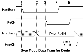
Byte Mode signal transitions:
IEEE 1284 EPP - Enhanced Parallel Port Mode
The Enhanced Parallel Port protocol was originally developed by Intel, Xircom and Zenith Data Systems, as a means to provide a high performance parallel port link that would still be compatible with the standard parallel port. This protocol capability was implemented by Intel in the 386SL chipset (82360 I/O chip). This was prior to the establishment of the IEEE 1284 committee and the associated standards work.
The EPP protocol offered many advantages to parallel port peripheral manufactures and was quickly adopted by many as an optional data transfer method. A loose association of around 80 interested manufacturers was formed to develop and promote the EPP protocol. This association became the EPP Committee and was instrumental in helping to get this protocol adopted as one of the IEEE 1284 advanced modes.
Since EPP capable parallel ports were available prior to the release of the 1284 standard, there is a small deviation between the pre-1284 EPP ports and 1284 EPP protocol. This will be made clearer later.
The EPP protocol provides four types of data transfer cycles:
Data cycles are intended to be used to transfer data between the host and the peripheral. Address cycles may be used to pass address, channel, or command and control information. These cycles can be viewed as just two different data cycles. The developer may use and parse the address/data information in any method that makes sense for a particular design. Table 1 describes the EPP signals and their associated SPP signals.
Table 5: EPP Signal Definitions
| SPP Signal | EPP Signal Name | In/Out | EPP Signal Description |
| nSTROBE | nWRITE | Out | Active low. Indicates a write operation High for a read cycle. |
| nAUTOFEED | nDATASTB | Out | Active low. Indicates a Data_Read or Data_Write operation is in process |
| nSELECTIN | nADDRSTB | Out | Active low. Indicates an Address_Read or Address_Write operation is in process. |
| nINIT | nRESET | Out | Active low. Peripheral reset. |
| nACK | nINTR | In | Peripheral interrupt. Used to generate an interrupt to the host |
| BUSY | nWAIT | In | Handshake signal. When low it indicates that is OK to start a cycle (assert a strobe), when high it indicates that it is OK to end the cycle (de-assert a strobe). |
| PE | user defined | In | Can be used differently by each peripheral. |
| SELECT | user defined | In | Can be used differently by each peripheral. |
| nERROR | user defined | In | Can be used differently by each peripheral. |
| DATA[8:1] | AD[8:1] | Bi-Di | Bi-directional address/data lines. |
Figure 4 is an example of a Data_Write cycle. The CPU signal nIOW is shown just to emphasize that this entire handshake occurs within a single I/O cycle.
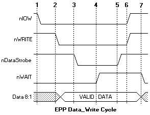
Data Write cycle phase transitions:
One of the most important features to note here is that the entire data transfer occurs within one ISA I/O cycle. The effect is that by using the EPP protocol for data transfer, a system can achieve transfer rates from 500K to 2M bytes per second. In this fashion, parallel port peripherals can operate at close to the same performance levels as an equivalent ISA plug-in card. The ability to get this level of performance from a parallel port attached device is one of the major features of the EPP protocol. With interlocked handshakes, the data transfer will happen at the speed of the slowest of the interfaces, the host adapter or the peripheral device. This 'speed adaptive' property is transparent to both the host and peripheral. All 1284 transfer modes are implemented with interlocking handshakes.
Interlocking refers to the criteria that each control signal transition is acknowledged by the opposite side of the interface. In the above diagram, nDataStrobe can be asserted because nWAIT is low, nWAIT deasserts in response to nDataStrobe be asserted, nDataStrobe deasserts in response to nWAIT being deasserted, and finally nWAIT asserts in response to nDataStrobe being deasserted. In this way the peripheral can control the setup time required for its operation. This is done in the following manner: the setup time is the time from the assertion of nDataStrobe to the deassertion of nWAIT, the peripherals controls this time. Interlocking also has the advantage of making the transfer cycle independent of the cable length. The Nibble, Byte, EPP and ECP modes all have interlocked protocols.
As previously mentioned, the pre-1284 EPP devices deviated from the 1284 protocol. At the start of the cycle, the nDataStrobe or nAddrStrobe would assert regardless of the state of the nWAIT signal. This means that the peripheral could not hold off the start of a cycle by having nWAIT deasserted. This is sometimes referred to as EPP 1.7, in reference to a Xircom proposal version 1.7. This is the version that Intel implemented in the original 82360 I/O controller. A 1284 EPP compatible peripheral will work properly with an EPP 1.7 version host adapter, but an EPP 1.7 peripheral may not operate properly with a 1284 compliant host.
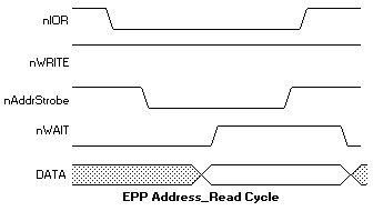
Figure 5: Example of an Address_Read cycle.
EPP Register Interface
The simplest software view of EPP is that of an extension to the register definitions for the standard parallel port. As shown earlier, the SPP consists of three registers, offset from the port's base address: Data port, Status port, and Control port. The most common EPP implementations expand this to use ports not defined by the SPP.
Table 6: EPP Register Definitions
| Port Name | Offset | Mode | Read/Write | Description |
| SPP Data Port | +0 | SPP/EPP | W | Standard SPP data port. No autostrobing. |
| SPP Status Port | +1 | SPP/EPP | R | Reads the input status lines on the interface. |
| SPP Control Port | +2 | SPP/EPP | W | Sets the state of the output control lines. |
| EPP Address Port | +3 | EPP | R/W | Generates an interlocked address read or write cycle. |
| EPP Data Port | +4 | EPP | R/W | Generates an interlocked data read or write cycle. |
| Not Defined | +5 to +7 | EPP | N/A | Used differently by various implementations May be used for 16 and 32 bit I/O. |
By generating a single I/O write instruction to 'base_address + 4', the EPP controller will generate the necessary handshake signals and strobes to transfer the data using an EPP Data_Write cycle. I/O instructions to the base addresses, ports 0 through 2, will cause behavior exactly as that as to a standard parallel port. This guarantees compatibility with standard parallel port peripherals and printers. Address cycles are generated when read or write I/O operations are generated to 'base_address + 3'.
Ports 5 through 7 are used differently by various hardware implementations. These may be used to implement 16 or 32-bit software interfaces, or used for configuration registers, or not used at all. For example, the FarPoint Communications F/PortPlus card has only an 8-bit data interface, but can be accessed using 32-bit I/O, for EPP data operations. The ISA controller will intercept the 32-bit I/O and actually generate 4 fast 8-bit I/O cycles. The first cycle will be to the addressed I/O port using byte 0 (bits 0-7), the second cycle will be to port+1 using byte 1, then port+2 using byte 2 and finally port+3 using byte 3. These additional cycles are generated by hardware and are transparent to the software. The total time for these four cycles will be less than 4 independent 8 bit cycles. The F/PortPlus card (from FarPoint Communications) maps 4 I/O ports (offset 4 to 7) to the internal EPP Data register. This enables the software to use 32-bit I/O operations for EPP data transfer. Address cycles are still limited to 8-bit I/O.
The ability to transfer data to or from the PC by the use of a single instruction is what enables EPP mode parallel ports to transfer data at ISA bus speeds. Rather than having the software implement an I/O intensive software loop, a block of data can be transferred with a single REP_IO instruction. Depending upon the host adapter port implementation and the capability of the peripheral, an EPP port can transfer data from 500K bytes to nearly 2M bytes per second. This data transfer rate is more than enough to enable network adapters, CD ROM, tape backup and other peripherals to operate at nearly ISA bus performance levels.
The EPP protocol and current implementations provide a high degree of coupling between the peripheral driver and the peripheral. What this means is the software driver is always able to determine and control the state of communication to the peripheral at any given time. Intermixing of read and write operations as well as block transfers are readily done. This type of coupling is ideal for many register-oriented or real-time controlled peripherals such as network adapters, data acquisition, portable hard drives, and other devices.
IEEE 1284 ECP Mode
The Extended Capability Port, or ECP, protocol was proposed by Hewlett Packard and Microsoft as an advanced mode for communication with printer and scanner type peripherals. Like the EPP protocol, ECP provides for a high performance bi-directional communication path between the host adapter and the peripheral.
The ECP protocol provides the following cycle types in both the forward and reverse directions:
The command cycles are divided into 2 types, Run-Length Count and Channel address.
Unlike EPP, when the ECP protocol was proposed, a standard register implementation was also proposed. This can be found in the Microsoft document "The IEEE 1284 Extended Capabilities Port Protocol and ISA Interface Standard" available from Microsoft Corp. This document defines features that are implementation specific which the IEEE 1284 standard could not address. These features include Run_Length_Encoding (RLE) data compression for the host adapters, FIFOs for both the forward and reverse channels, and DMA as well as programmed I/O for the host register interface.
The RLE feature enables real time data compression that can achieve compression ratios up to 64:1. This is particularly useful for printers and scanners that are transferring large raster images that have large strings of identical data. In order for the RLE mode to be enabled both the host and the peripheral must support it.
Channel addressing is, conceptually, a little different than the EPP addressing. Channel addressing is intended to be used to address multiple logical devices within a single physical device. Think of this in terms of a new multi-function device such as FAX/Printer/Modem. Within one physical package, having a single parallel port attached, there is a printer, fax and modem. Each of these separate functions can be thought of as separate logical devices within the same package. Using the ECP channel addressing to access each of these devices, you could receive data from the modem data device while the printer data channel is busy processing a print image. With the compatibility mode protocol, if the printer gets busy then no more communication can occur until the printer data channel if free. With ECP, the software driver simply addresses another channel and communication can continue.
As with the other 1284 modes, the ECP protocol redefines the SPP signals to be more consistent with the ECP handshake. Table 1 describes these signals.
Table 7: ECP Mode Signals
| SPP Signal | ECP Mode Name | In/Out | Signal usage when in ECP Mode data transfer |
| nSTROBE | HostClk | Out | Used with PeriphAck to transfer data or address information in the forward direction. |
| nAUTOFEED | HostAck | Out | Provides Command/Data status in the forward direction. Used with PeriphClk to transfer data in the reverse direction. |
| nSELECTIN | 1284Active | Out | Set high when host is in a 1284 transfer mode. |
| nINIT | nReverseRequest | Out | Driven low to put the channel in reverse direction. |
| nACK | PeriphClk | In | Used with HostAck to transfer data in the reverse direction. |
| BUSY | PeriphAck | In | Used with HostClk to transfer data or address information in the forward direction. Provides Command/Data status in the reverse direction. |
| PE | nAckReverse | In | Driven low to acknowledge nReverseRequest. |
| SELECT | Xflag | In | Extensibility flag. |
| nERROR | nPeriphRequest | In | Set low by peripheral to indicate that reverse data is available |
| DATA[8:1] | DATA[8:1] | Bi-Di | Used to provide data between the peripheral and host. |
Figure 6 shows two forward data transfer cycles. When HostAck is high it indicates that a data cycle is taking place. When HostAck is asserted low, a command cycle is taking place and the data represents either an RLE count or a Channel address. Bit 8, of the data byte is used to indicate RLE vs. Channel address. If bit 8 is 0, then bits 1-7 represent a Run_Length Count (0-127). If bit 8 is 1, then bits 1-7 represent a Channel address (0-127). Figure 6 shows a data cycle followed by a command cycle.
Figure 6: Two forward data transfer cycles.
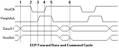
Forward Transfer phase transitions:
NOTE: Since ECP transfers are loosely coupled, with a FIFO possibly on both sides of the interface, it is important to note at which step the data is considered 'transferred'. This point occurs at step 4, when the HostClk goes high. At this time, the data should be clocked in to the peripheral, and any data counters updated. There is a condition in the ECP protocol that could cause the transfer to abort at between steps 3 and 4. In this case the data should not be considered to have been transferred.
Figure 7 shows a reverse channel command cycle followed by a reverse channel data cycle. The I/O read or write strobes are not shown in these figures. This is because the ECP FIFOs are used to decouple the ISA data transfers, either DMA or programmed I/O, from the actual host/peripheral data transfers. It is this decoupling of the transfer states that makes the ECP protocol a 'loosely coupled' protocol. The software driver does not know the exact state of the data transfers. If a large block is being transferred via DMA, the driver does not know if the 123rd byte is being transferred or the 342,201st byte. As in the case of printers, the software may not care. The only concern is whether the transfer was completed or not.
Figure 7 shows another of the differences between the ECP and EPP protocols. With EPP, the software driver may intermix read and write operations without any overhead or protocol handshaking. With the ECP protocol, changes in the data direction must be negotiated. The host must request a reverse channel transfer by asserting nReverseRequest and then wait for the peripheral to acknowledge the request by asserting nAckReverse. Only then can a reverse channel data transfer take place. In addition, since the previous transfer may have been DMA driven, the host software must either wait for the DMA to complete, or interrupt the DMA, backflush the FIFO to determine the exact transferred byte count, and then request the reverse channel. This adds a fair amount of overhead with peripherals that require a lot of intermixed reading and writing of registers or small buffers.
Figure 7: A reverse channel command cycle followed by a reverse channel data cycle.
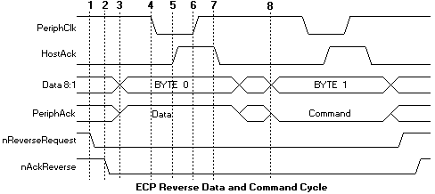
Reverse Transfer phase transitions:
ECP Software and Register Interface
The Microsoft specification, "The IEEE 1284 Extended Capabilities Port Protocol and ISA Interface Standard", defines a common register interface for ISA based 1284 adapters with ECP. This specification also defines a number of operational modes that the adapter can operate under. Table 8 identifies these modes.
Table 8: Extended Control Register (ECR) Modes
| Mode | Description |
| 000 | SPP Mode |
| 001 | Bi-directional mode (Byte mode) |
| 010 | Fast Centronics |
| 011 | ECP Parallel Port mode |
| 100 | EPP Parallel Port mode * |
| 101 | Reserved |
| 110 | Test mode |
| 111 | Configuration mode |
* This mode is implemented by the SMC FDC37C665/666 controller and is not defined by the ECP specification. Most 1284 I/O controllers implement the EPP mode in a similar fashion.
The register model for an ECP port is similar to that of the standard parallel port, but takes advantage of a significant design oddity of the ISA bus architecture. In the IBM compatible PC architecture, only the first 1024 I/O ports, or addresses, are used. This is the basic I/O space of 0x000h to 0x3ffh. In order to address this range of addresses, only 10 address bits are needed (AD0-9). In order to save cost, older PC's only drove and decoded these address bits on the ISA bus and therefore limited the available I/O space to these 1024 registers. Newer PC's, actually drive and decode more address bits, enabling a larger available I/O space. This creates, in effect, multiple 'pages' of the first 1K I/O ports. A software driver can access these pages by adding 1024 (0x400h hex notation) to the base address being accessed. Therefore, addressing addresses 0x378h and 0x778h can access 2 registers on two separate pages, but be guaranteed not to interfere with any other installed ISA device. The advantage is that by using this 'aliasing' effect, new cards can have 'hidden' registers, thus expanding the available number of registers available, and still maintain compatibility with older ISA cards that only decode 10 address bits.
The ECP register model takes advantage of this and defines 6 registers that only require 3 actual I/O ports. Table 9 identifies these registers. Note that the register definition may be dependent upon the current mode of operation. The ECR register is the most important aspect of this register configuration. This is the register that is used to set the current operational mode. Additionally, this register can be used by software to determine if an ECP-capable port is installed in the PC. Detection software can try to access any ECR registers by adding 0x402h to the base address of the LPT ports identified in the BIOS LPT port table.
Table 9: ECP Register Description
| Offset | Name | Read/Write | ECP Mode | Function |
| 000 | Data | R/W | 000-001 | Data Register |
| 000 | ecpAfifo | R/W | 011 | ECP Address FIFO |
| 001 | dsr | R/W | all | Status Register |
| 002 | dcr | R/W | all | Control Register |
| 400 | cFifo | R/W | 010 | Parallel Port Data FIFO |
| 400 | ecpDfifo | R/W | 011 | ECP Data FIFO |
| 400 | tfifo | R/W | 100 | Test FIFO |
| 400 | cnfgA | R | 111 | Configuration Register A |
| 401 | cnfgB | R/W | 111 | Configuration Register B |
| 402 | ecr | R/W | all | Extended Control Register |
This paper will not attempt to describe all the functions of the ECP registers. For information regarding the register usage and bit definitions, please refer to the Microsoft document or the I/O controller data sheet.
It should be noted that if the port is in either standard parallel port mode or bi- directional mode, then the first 3 registers behave exactly as a standard parallel port. This way, compatibility with older devices and device drivers is maintained.
Usage of this port is similar to that of the EPP port. An operational mode is written to the ecr register, and then data transfer is accomplished by writing or reading from the appropriate I/O port. All of the handshaking is automatically generated by the interface controller. The major difference is that the ECP port is meant to be driven by DMA rather than explicit I/O operations. Again, this is a loosely coupled interface that is targeted primarily at peripherals that interchange large blocks of data.
IEEE 1284 Negotiation
The previous sections have identified all of the modes of an IEEE 1284-capable interface. Peripherals are not required to implement all of the modes. This being the case, a method is needed for a host platform to determine what the capabilities of the attached peripheral are, and to have a controlled method by which to set the interface into one of the modes.
The concept of negotiation was developed to fill this need. Negotiation is a sequence of events on the parallel port interface that would not effect an older 'legacy' device but would provide identification of a 1284 peripheral. The concept is that an older device will not respond to the negotiation sequence and therefore the host would remain in a compatible mode state, while a 1284 peripheral would respond to the sequence and could then be set to any of the peripheral and host supported modes.
During the negotiation phase, the host places a request on the data lines and then initiates the negotiation sequence. The request can be to put the interface into a particular mode, or request a device ID from the peripheral. Device ID will be discussed later. Figure 8 shows the basic Negotiation sequence.
The Extensibility byte is used during negotiation to request that the peripheral enter a specific transfer mode, or to request that the peripheral send a device ID that will allow the host to identify the type of attached peripheral. The device ID can be returned in any reverse channel mode, other than EPP. Table 10 describes the extensibility byte and allowable values. The XFlag is used by the peripheral for acknowledgment that the requested mode is available. The XFlag will always be set to one (#6 in Figure 8) as a positive acknowledgment for all requests except for Nibble mode reverse channel. All 1284-compliant devices are required to support Nibble mode for reverse channel operation. The Extensibility Link request bit is used to provide a mechanism for future expansion and addition of new operational modes and features.
Negotiation and device ID are key features for the future ability of PC platforms to determine system configuration and to include parallel port attached peripherals in this determination.
Table 10: Extensibility Byte Bit Values
| Bit | Description | Valid Bit Values (8765 4321) |
| 8 | Request Extensibility Link | 1000 0000 |
| 7 | Request EPP Mode | 0100 0000 |
| 6 | Request ECP Mode with RLE | 0011 0000 |
| 5 | Request ECP Mode without RLE | 0001 0000 |
| 4 | Reserved | 0000 1000 |
| 3 | Request Device ID | Return data using mode: 0000 0100 - Nibble Mode 0000 0101 - Byte Mode 0001 0100 - ECP Mode without RLE 0011 0100 - ECP Mode with RLE |
| 2 | Reserved | 0000 0010 |
| 1 | Byte Mode | 0000 0001 |
| non | Nibble Mode | 0000 0000 |
Figure 8: Basic Negotiation sequence.
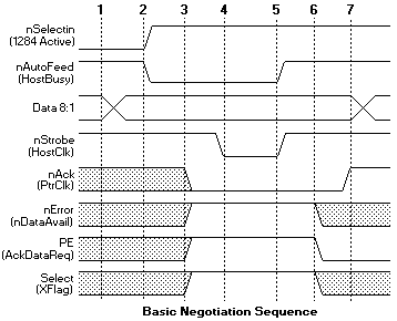
1284 Negotiation phase transitions:
IEEE 1284 Electrical Interface - Cable
The original parallel port did not have a defined electrical specification that identified the driver, receiver, termination and capacitance requirements in order to guarantee any compatibility between devices. Host adapters and peripherals were built with any number of pull-up values on the control lines, open collector or totem pole drivers for the data and control lines, and most offensive of all, up to 10,000pF capacitors on the data and strobe lines. This type of design variation makes it impossible to create a new interface protocol without explicitly defining the required electrical parameters with which to guarantee operation.
The 1284 standard defines two levels of interface compatibility, Level I and Level II. The Level I interface is defined for products that are not going to operate at the high speed advanced modes, but need to take advantage of the reverse channel capabilities of the standard. The Level II interface is for devices that will operate in the advanced modes, with long cables, and at the higher data rates. This discussion will deal primarily with Level II interfaces. Please refer to the standard for the full requirements for either a Level I or Level II interface.
The requirements for the Level II drivers and receivers are defined at the connector interface. The driver requirements are:
Like the driver requirements, the receiver requirements are defined at the connector interface. The receiver requirements are:
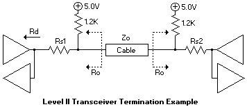
Figure 9 shows the recommended termination for a driver/receiver pair. Ro represents the output impedance at the connector. It is intended that this impedance match the cable impedance so as to minimize the noise caused by mismatched impedances. Depending upon the type of driver used, a series resistor, Rs may be required to obtain the correct impedance. Figure 10 shows the recommended termination for a Level II transceiver pair, such as the data lines.
Figure 9: Recommended termination for a driver/receiver pair.
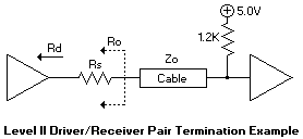
Figure 10: Recommended termination for a Level II transceiver pair.
There are products being introduced by some companies that provide integrated solutions for a 1284 Level II interface. These include active drivers and receivers as well as resister sip networks.
NOTE: When ECP was first introduced, Microsoft made a recommendation for an electrical and termination requirement that was not consistent with the 1284 specification. This included an AC terminator for each of the lines. This suggestion has been retracted and the current recommendation is to use the interface defined in the IEEE 1284 specification.
IEEE 1284 Cable Assemblies
In order to guarantee high performance operation, 10M cable lengths, and interoperability among various platforms and peripherals, the 1284 standard defines the characteristics for the cable assemblies.
Contrary to popular belief, there is no such thing as a 'standard' parallel printer cable. This typically refers to a cable assembly with a DB25 male on one end and a 36 pin Champ plug connector on the other end. Internally, the cables may have from 18 to 25 conductors, with 1 to 8 ground wires, they may have foil shielding and/or braid, and possibly a drain wire. With this type of assembly there is no way to control the cable impedance, crosstalk, capacitance and performance. This type of assembly is fine for operation at 10K bytes per second at 6 ft., but will not work reliably at 2M byte per second at 30 ft. cable lengths.
Some of the parameters for a compliant 1284 cable assembly include:
Standard cable lengths are available in 10 ft., 20 ft. and 30 ft. from some manufacturers. Since this cable has such good performance there is no need to be limited to a 6 ft. cable assembly.
HTML transcription by UZ.
| Legal | Copyright | top |