This command can be used after having checked the connections between elements for example, or to fill slight gaps between joined surfaces.
-
Click Healing
 .
.The Healing Definition dialog box appears. 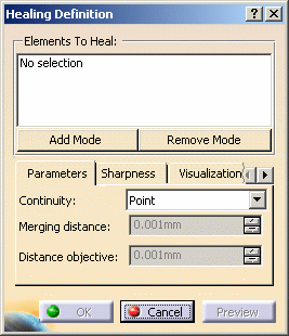
-
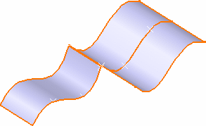
Select the surfaces to be healed.
-
You can edit the list of elements in the definition list:
-
by selecting elements in the geometry:
-
Standard selection (no button clicked):
when you click an unlisted element, it is added to the list
when you click a listed element, it is removed from the list -
Add Mode:
when you click an unlisted element, it is added to the list
when you click a listed element, it remains in the list -
Remove Mode:
when you click an unlisted element, the list is unchanged
when you click a listed element, it is removed from the list
-
-
by selecting an element in the list then using the Remove Selection\Clear Selection contextual menu items.

If you double-click Add Mode or Remove Mode, the chosen mode is permanent, i.e. successively selecting elements will add/remove them. However, if you click only once, only the next selected element is added or removed.
You only have to click the button again, or click another one, to deactivate the mode. -
-
Define the distance below which elements are to be healed that is deformed, so that there is no more gap, using the Merging distance as described in Joining Geometry.
Elements between which the gap is larger than the indicated value are not processed.
In our example, we increase it to 1mm.
-
You can also set the Distance objective, i.e. the maximum gap allowed between two healed elements. By default it is set to 0.001 mm, and can be increased to 0.1 mm.
-
Click Preview to visualize the maximum deviation value between the input surfaces and the result in the 3D geometry.
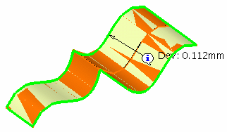

The value is displayed on the edge or the face onto which the deviation is maximal, not exactly where the maximum deviation is located. -
Click OK to create the healed surfaces.
The surface (identified as Heal.xxx) is added to the specification tree. 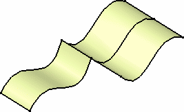

You can check the Surfaces' Boundaries option from the Tools > Options menu item, General > Display > Visualization tab to display the boundaries. This may be especially useful when selecting, and also to identify gaps.
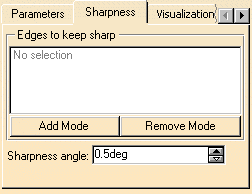
Sharpness tab
- Provided the Tangent mode is active, you can retain sharp
edges and selecting one or more edges.
You can edit the list of edges as described above for the list of elements to be healed. - The Sharpness angle allows to redefine the limit between a sharp angle and a flat angle. This can be useful when offsetting the resulting healed geometry for example. By default this angle value is set to 0.5 degree.
- In some cases, depending on the geometry configuration and the set
parameters, the Multi-Result Management dialog box is displayed.
Refer to Managing Multi-Result Operations for further information.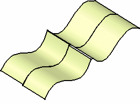
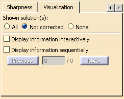
Visualization tab
It lets you define the way the messages are displayed on the smoothed element.
- All the messages, that is to say the messages indicating
where the discontinuity remains as well as those indicating where the
discontinuity type has changed (in point (><) and tangency (^))
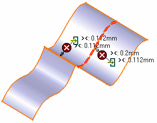
- only the messages indicating where the discontinuity is Not
corrected and still remains
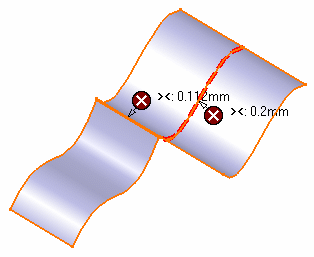
- None of the messages
- Display information interactively: only the pointers in
the geometry are displayed, above which the text appears when passing the
pointer
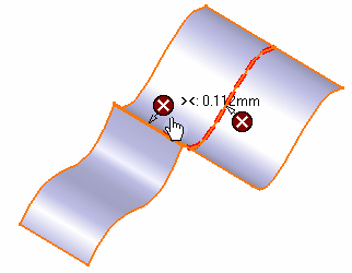
- Display information sequentially: only one pointer and
text are displayed in the geometry, and you can sequentially move from
one pointer to another using the previous/next buttons
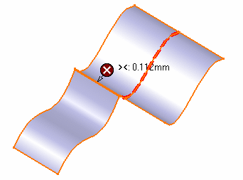
![]()
