Creating a Specifications Catalog
|
|
This task shows you how to create a specifications catalog for products that use parametric parts.An example from the HVAC Design workbench is used here. The process for other workbenches is the same - simply use the relevant CATfct file and terminology. For instance, in the Waveguide workbench you would use Waveguide Part instead of HVAC Part. If you are only familiar with a specifications catalog as used in Piping or Tubing, you should note that the process is somewhat different in applications where parametric parts are used, as in HVAC. See also Creating a Specifications Catalog in the ENOVIA section. | |
|
|
A specifications
catalog allows you to specify which parts can be used for a certain project
or part of a project. The main catalog typically contains parametric parts,
and most values are applied at parts placement time - the size of a duct is
derived from the run, for instance. However, in many circumstances you will
only want to use parts that have certain properties - for instance, design
considerations may require that only ducts with a nominal size between 4
and 8 inches be used. You achieve this by specifying in a specifications
catalog what the properties (and values) should be for the parts you want
to use. When you place parts using the specification, you will only be able
to use parts that fall within your stated criteria. Using the example given
above, even if a designer has a 10-inch run, he will not be able to place a
10-inch duct on it because the specification restricts duct size to between
4 and 8 inches. Your specifications are defined in the rules tables. As explained below, typically you will create a specification named 'Default'. The rules contained in this specification apply to all the other specifications - if they are not defined in that specification. When you are placing a part using a particular specification, the application first determines if relevant rules are defined under that specification. If they are defined then it will use those rules. If they are not defined then it will use the rule under the Default specification. So, you can specify a duct nominal size of between 2 and 12 inches in the default specification. In Spec A you want to restrict the size to between 2 and 6 inches, so you add a table restricting the user to that size. In Spec B you don't have any particular requirement, so you do not add any table and the application will then use the sizes as listed in the Default catalog. When you use the provided template to create a specifications catalog you must use the rules supplied with this application. You can modify or delete them (see Modifying Design Rules) but you cannot add new rules. |
|
|
|
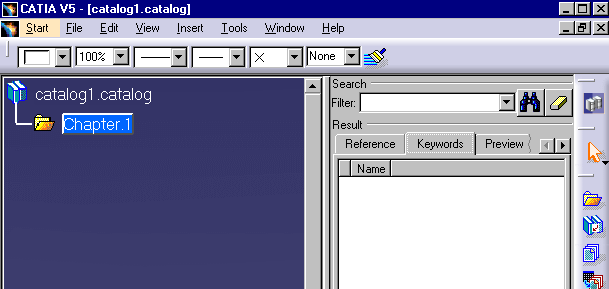
1. | Click Start - Infrastructure - Catalog
Editor to start the Catalog Editor.
|
| 2. | Open the CATfct file associated with your
application. To do this, click the Open User Dictionary button
|
|
|
|
You can add default rules to your specifications catalog (explained below). These rules appear in a separate chapter named "Default". The rules in the Default chapter will apply to all specifications that you create. This saves you having to associate rules for each specification that you create. | |
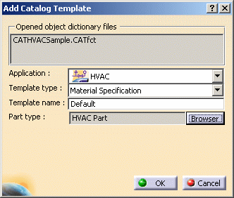
| 3. | Click the Add Catalog Template
button
|
|
| 4. | Select the application (HVAC), and
then click on the down arrow in the Template Type field and make your
selection - in this case Material Specification. Enter a name for the
specifications catalog in the Template Name field. If you are creating
default rules you must enter the name Default. Click on the Browser
button next to the Part Type field and make your selection. In this case it
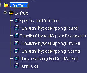
is HVAC Part because this is an HVAC specifications catalog. Click OK. The
Default chapter and the default design rules display in the specifications
tree. There will be differences in the rules that display in other
applications like Waveguide.
In applications where you can create both a material specifications catalog and insulation specifications catalog, there may be differences in the design rules that appear in each type of catalog. |
|
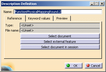
| 5. | You now need
to associate the actual design rules table (which is how design rules are
defined) to each of the design rules in the specifications tree. Double
click on a rule and then click the Add Component button
|
|
| 6. | Click the Select Document
button. In the File Selection box that displays navigate to the directory
where the design rules tables are. They are CATProduct type files. (From
Release 13 you can link directly to the text tables that define each rule.)
The default directory is intel_a\startup\EquipmentandSystems\XXX\Specification
(where XXX is your application) and then the specification itself, say
A-GA-W01. (These may be a further sub-directory, such as
MaterialSpecification.) Open the A-GA-W01 directory and select the text
file (or table) that corresponds to the rule that you double-clicked, in
this case FunctionalPhysicalMappingRound. Click Open on the File Selection
box and OK on the Description Definition box. The table will be associated
with the rule and display in the Catalog Editor.
NOTE: If you are working in the ENOVIA database then you cannot link directly to a text file as explained above. Instead you must link to the CATProduct containing the design rule. In addition, the text file must be stored within the CATProduct (using the Duplicate in CATIA option).
If you click on the Reference tab you will be able to see the full directory path. If you link to the CATProduct you will only see one file listed, as above. If you link to the text files then you will need to link to tables for each part type referenced by the rule: the sample part types are branch, branch connection, duct, inline, reducer and valve. So, if you were linking to the text files you would see six files listed above. If you add new part types then you must link those to the rule. Also, if you are linking to the text files then you must enter the actual function name in the Name field of the Description Definition dialog box (Step 5). You can see the function names in the CATProduct file associated with each rule. |
|
| 7. | Associate all the rules with the corresponding tables using the procedure described above. | |
| 8. |
After you
have associated the rules in the Default catalog, you can create one or
more specifications. To do this, use the Add Catalog Template command as
explained in Step 3. Enter a name in the Chapter Definition dialog
box, say TestSpec. Link the rules to tables that contain your data,
following the process described above. If you do not need to have your own
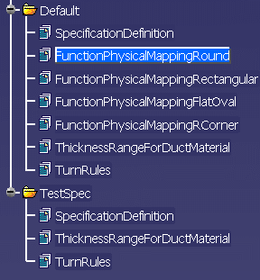
tables for any of the rules you can delete it. In the image below the user
has chosen to delete most of the rules from the specification TestSpec.
|
|
|
|
Be careful when adding data to existing tables, or adding new tables. They must follow the existing structure. See Modifying Design Rules for more information. | |
| 9. | Click OK to create the catalog. Save it when done. | |
![]()
