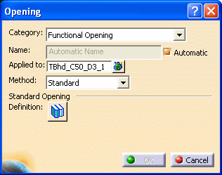
With your 3-D session open, click the
Opening button ![]() to
display the Opening dialog box.
to
display the Opening dialog box.

2.
The name of the opening is assigned automatically, using the object naming rules. If you want to assign your own name to the opening, uncheck the Automatic box and enter a name.
When you select more than one object, the selected number of objects display as elements in Applied To field.
Click the button beside the Applied To field and the Elements List displays, listing the objects you selected.
Select an object on the list that you want to replace, and click the Replace button. Select an object in the 3-D session, and this object displays on the Elements List in place of the original one.
You can also remove objects from the list. Select the objects you want to remove, and click the Remove button. The selected objects are removed from the Elements List.
Click Close when you have made all the necessary changes.

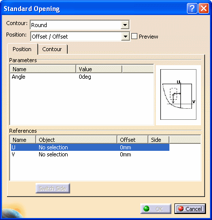
Contour is the shape of the opening.
Position is the strategy used to determine where an opening is placed. An image of the opening reflecting the selected position strategy displays in the dialog box.
By entering references for the U and V directions, you can create multiple openings at specified positions. See explanation of the References pane below.
In the Parameters pane, change the angle of the contour under Value as necessary.
Information listed in the References pane depends on the Position selected.
NOTE: You can multi-select references in the U direction and create multiple openings. (The Elements List displays whenever you can multi-select, listing your selections.) You can only select one V direction except for Mid-Dist/Mid-Dist.
Offset/Offset - Offset from reference elements in U and V directions.
Half-Height /Offset - Offset from a reference element for U, then position in V halfway between plate edges.
Mid-Dist/Offset - Position halfway between two elements for U, and offset from another reference element for V.
Mid-Dist/Mid-Dist - Position halfway between two elements in U, and halfway between two other elements in V.
Half-Height/Mid-Dist - Position halfway between two elements in U, then position in V halfway between plate edges.
When Chain is not selected, you position openings between each pair of references (for example, between 1 and 2, 3 and 4, 5 and 6.
Selecting Chain allows you to position openings between every reference (for example, between 1 and 2, 2 and 3, 3 and 4, 4 and 5, 5 and 6.
You can click the Switch Side button to change the direction from the reference object where the opening will be placed.
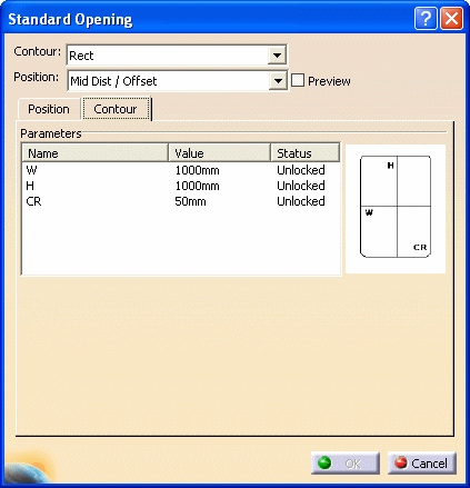
Select a row and change the dimensions of the contour (under Value) as necessary.

NOTE: You can only change the parameter values if the Status is Unlocked.
Your 3-D session displays the changed values when the Preview checkbox is selected.

You can modify information only for the selected opening (you cannot multi-select).
You cannot change the position strategy of the opening.