Placing a Hole on a Part
|
|
This task shows how to define and place a hole on a part. | |
|
|
When you place a hole you are
creating a point from which to route so as to add a run and smaller duct,
pipe or tube. When you define the hole you are editing certain
default parameters such as the diameter, orientation and tangent direction
to meet the requirements of the hole you want to create and route from.
There is no length (or depth) parameter to a hole although it appears so
when placed in your document.
When defining and placing a hole you should set the connector display options. Go to Tools - Options - Equipment & Systems. Select the Display tab, scroll down to 3D Viewer Display Options and check the Part connections and Part connectors options. |
|
|
|
1. | With your document open, click the Place Hole
button
|
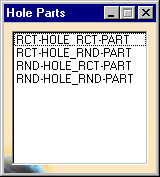
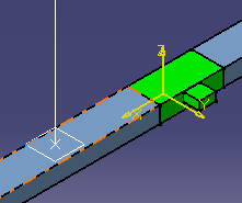
| 2. | Select the desired hole type. The tangent-plane
appears as a visual aid. Move it to the location you have chosen for the
hole and click.
|
|
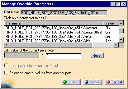
| 3. | When you click to place the hole the Manage Override
Parameters dialog box opens displaying the list of parameters that you can
edit.
|
|
| 5. | Edit the parameters as necessary to meet the intended design. Click Apply after you edit each parameter to update the product. | |
| 6. | When finished editing the parameters click OK. The hole is placed. To modify the hole further, see Modifying a Hole. | |
|
|
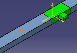
When placed, the hole has a connector from which you can continue routing. | |
|
|
||