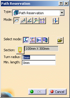
The Path Reservation dialog box displays.

Point-to-point
Orthogonal
Directional
Branch at Center. See Branching a Path Reservation
In addition, if you place the compass on an object, the Use Compass Origin button
displays. If you click the button and start to route, the route starts from the compass origin. If you are in the middle of routing, the compass origin serves as a routing point.
Click one of the Select Mode buttons, default is No Filter. The Select Mode buttons allow you to define where you can start routing from.
No Filter: No filters are applied and you can route from any routable object or in space.
In Space: Routing will be in space. This is useful when you have a large object in the background, such as a ship structure, and you want to be able to route in space.
Only Part Connectors: Select this to be able to route from part or equipment connectors only.
Select part to display connector list: This button allows you to use a dialog box to select the connector on which to place a part, and is useful in busy documents. Click this button if you want to select the connector on which to place your part by using a dialog box, instead of selecting the connector in the viewer. With your document open, select the part you want to place, click the Select part to display connector list button and choose the part on which you want to place your part. A Selected Part dialog box will display, showing all the connectors on your selected part. The selected connector will be highlighted, and will be orange in the viewer. Select the connector on which you want to place your part and click OK.
Import Node Points: This allows you to route using predefined node points. See Routing with Defined Nodes for more information.
a. Click the Section Type button
.
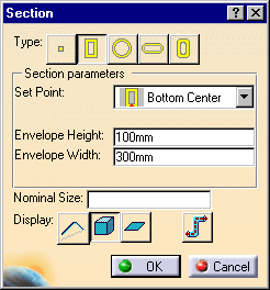
The Section dialog box displays.
b. Define the section type and the corresponding parameters for each of them:
No Section
Rectangular
- Set Point
- Envelope height
- Envelope width
- Display
- Nominal size
Circular
- Set Point
- Envelope diameter
- Nominal size
- Display
Flat Oval
- Set Point
- Envelope height
- Envelope width
- Display
Radius Corner
- Set Point
- Envelope Height
- Envelope Width
- Radius Corner
- Display
c. You can select the Display buttons
to choose a display mode of Line/Curve, Solid or Flat.
d. Click the Display Centerline button
to show the centerline of the run. This appears as a dashed yellow line. In addition, a dashed blue line appears to display the Set Point setting. This feature works in all display modes, Line/Curve, Solid and Flat.
e. Select OK on the Section dialog box.
To do this, click the Path Reservation button, then click the left mouse button once on the path reservation whose values you want as the default. Make sure the entire path reservation is selected, and not just one segment or node. It will be easier to select the path reservation in the specifications tree. You can choose to key in a value for the turn radius.
Double-click the last point to stop routing.
![]()

