![]()
|
|
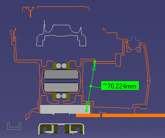
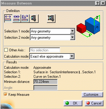
Distance & Band Analysis lets you measure minimum distance at product level, irrespective of whether or not the section view is a filled view. The result you obtain is the minimum distance between the sections of selected products (model, CATPart, etc.). Measure Between lets you measure minimum distance between edge primitives or at element level depending on whether the section view is a filled view or not:
|
|||||||||
|
|
This task explains how to measure minimum distance in the Section viewer. |
|||||||||
|
|
No sample document is provided. |
|||||||||
|
|
|
|||||||||
Measure at Element level
|
||||||||||
 |
||||||||||
 |
||||||||||
Between Edge PrimitivesImportant: To be able to measure the minimum
distance between edge primitives, you must de-activate the Section
Fill
The result is the minimum distance between edge primitives. |
||||||||||
|
|
||||||||||
|
|
||||||||||
|
If the Keep Measure option is selected, measures made using measure tools in the Section viewer are added to the specification tree under the Section entry. These measures can only be seen in the Section viewer and are not visible in the 3D document.
|
||||||||||
|
|
||||||||||