![]()
This task explains how to measure minimum distance and
distance along X, along Y and along Z between products.
In this step-by-step scenario, you will measure the minimum distance and
the distance along z between products in two different selections.
![]()
Measuring distances along a direction (X, Y or Z) is a P2 functionality.
Measuring Minimum Distances & Distances Along
X, Y, Z
![]()
Insert the following sample cgr files: ATOMIZER.cgr, BODY1.cgr, BODY2.cgr, LOCK.cgr, NOZZLE1.cgr, NOZZLE2.cgr, REGULATION_COMMAND.cgr, REGULATOR.cgr, TRIGGER.cgr and VALVE.cgr.
They are to be found in the online documentation filetree
in the common functionalities sample folder cfysm/samples.
![]()
-
Click Distance and Band Analysis
 in the DMU Space Analysis toolbar, or select Insert >
Distance and Band Analysis from the menu bar to calculate
distances. The Edit Distance and Band Analysis dialog box
appears.
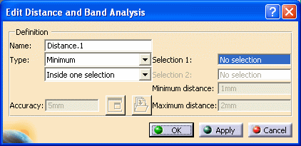

The default distance analysis is measuring the minimum distance inside one selection
-
Ensure that the first Type drop-down list box is set to Minimum.

For more information: read Defining Measurement Type
-
Select a product, for example the Trigger.
-
Click the second Type drop-down list box and select Between two selections.
-
Select another product, for example the Regulation_Command.

Notes:
-
Any sub-assembly in the specification tree is considered a valid selection.
-
Click in selection fields (fields turn dark blue) to view your selections and be certain that you have selected the products you intended: selected products are highlighted.
-
Continue clicking to select as many products as you want. Products will be placed in the active selection. To de-select products, reselect them in the specification tree or the geometry area.
-
-
Click Apply to calculate the distance:
-
If necessary, pan, zoom and/or rotate in the Preview window to visualize the results better.

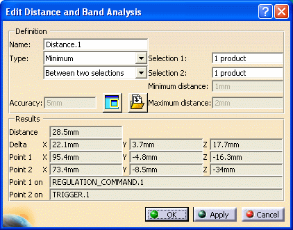
Minimum distance and other information identifying all distance components is given in the expanded dialog box. X, Y, Z coordinates of start and end points on products selected for the distance calculation as well as products themselves are identified.
-
Click the Type drop-down list box and select Along Z.
-
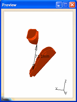
Click Apply. Results are calculated and displayed in the dialog box and Preview window. The Edit Distance and Band Analysis dialog box expands to show the results.

-
Click OK in the Edit Distance and Band Analysis dialog box when done.
The distance definition and results are kept as a specification tree feature. This means you can run the measurement again after, for example, moving one of the products or modifying the contents of a group: distance results will be updated to reflect changes made.

You can also view the results in a separate viewer. To do
so, click
Results window
![]() in the Edit Distance and Band Analysis dialog box. Object
viewing commands and commands in the Window menu are available in this
window. For example, using the Windows menu, you can tile the results
window and the original document window vertically or horizontally.
in the Edit Distance and Band Analysis dialog box. Object
viewing commands and commands in the Window menu are available in this
window. For example, using the Windows menu, you can tile the results
window and the original document window vertically or horizontally.
You can use other DMU Space Analysis toolbar commands in the Results window to, for example, measure surfaces.
Defining Measurement Types
|
|
Select the required type from the drop-down list box:
-
Minimum
-
Along X (P2 only)
-
Along Y (P2 only)
-
Along Z (P2 only)
-
Band analysis (P2 only) and About Distance and Band Analysis
Defining Computation Types
|
|
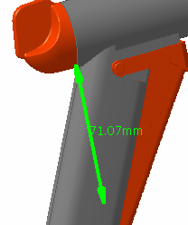
A Preview window appears visualizing selected products and the minimum distance (represented by a line, two arrows and a value).
You can change the default display setting for the Preview
window using the
Tools > Options..., Digital Mockup command (DMU Navigator tab)
If you close the Preview window, to open it again:
-
Click Results window
 in the Edit Distance and Band Analysis dialog box
This opens the dedicated results window. -
Click Results window
 a second time
The results window is closed and the Preview window is restored.
|
|
If however, you close the Results window (using the Close button in the title bar), the Preview window will not be restored. |
Modifying the Color, Linetype and
Thickness of the Distance Result
To make it easier to read your result, you can specify different properties for distance result. This is done via the Properties command or via the Graphic Properties toolbar.
The Properties command lets you change the color, linetype and thickness of the current distance result (under Lines and Curves in Graphics tab).
To access properties:
-
Right-click the specification tree feature and select Properties.
-
In the dialog box, click the Graphic tab.
|
|
You can also change these properties via the Graphic Properties toolbar.
To do so:
-
Select the feature in the specification tree.
-
Set the linetype, thickness and/or plane color in the Graphic Properties toolbar.
To return to the initial colors, select No color.
P1 Functionalities

In DMU-P1, you can measure the minimum distance only between products in the same selection, between products in the selection and other products in the document, or between products in two different selections and view the results in a separate viewer.
|
|
![]()
The Distance and Band Analysis capability also lets you run a band analysis to compute and visualize the areas on products corresponding to a minimum distance within a user-defined range.
![]()


