Isoparametric machining is an operation which allows you to select strips of faces and machine along their isoparametrics.
To create the operation you define:
- the
geometry of the part to machine
 ,
, - the
parameters of the machining strategy
 ,
, - the
tool to use
 ;end mill,
 face mill
 , conical mill
 and T-slotter
 tool can
be used for this operation,
 - the feedrates and spindle speeds
 ,
, - the macros .

Only the geometry is obligatory, all of the other requirements have a default value.
Multi-Edition
You can modify the parameters of two or more Isoparametric machining
operations in one shot by means of the Selected Objects > Definition...
contextual command.
See Editing Parameters of Several
Isoparametric machining Operations.
- make the Manufacturing Program current in the specification
tree if you want to define an operation and
the part/area to machine at the same time, - or select a machining feature from the
list if you have already defined the area to machine and
now you want to define the operation to apply to it.
Below we are going to see how to do the first of these.
Open file Basic2.CATPart then select Machining > Surface Machining in the Start menu.
-
Click Isoparametric Machining
 .
.
An Isoparametric Machining entity and a default tool are added to the program.
The dialog box opens at the geometry tab page .
.
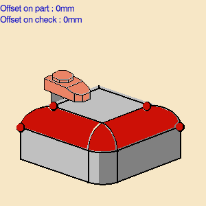
This page includes a sensitive icon to help you specify the geometry to be machined.


- The area that represents the part surface is colored red
indicating that the geometry is
equired for defining the area to machine. - The four points on the area to machine are also obligatory.
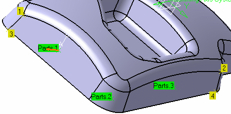
They are required in order to define the direction of the isoparameters (from 1 to 2). - All of the other geometry parameters are optional.
- The tool path will always start on point 1 and finish on point
4.
This means that, if your parameters are set in such a way that, under normal circumstances,
the tool path would end on point 3, the tool path will be computed in such a way as to ensure
that it finishes on point 4.
In order to do this the last five passes may be closer together than the others (by 20%).
- The area that represents the part surface is colored red
indicating that the geometry is
-
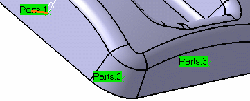
Click the red part surface in the icon and then select these faces in the viewer.

The faces must be connected to each other. -
Click a red point in the icon and select the four corner points of the part surface.
The part surface and corner points of the icon are now colored green indicating
that this geometry is now defined.

-
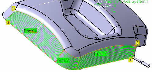
Click Tool Path Replay
 .
.
A progress indicator is displayed.
You can cancel the tool path computation at any moment before 100% completion.

![]()