An offset group can contain one or more offset area(s).
You can apply an overall offset LINK to an offset group.
An offset area is a group of faces (at least one) with an offset value (with
respect to the original part)
and a color to identify it.
They can be edited or deleted once they have been created.
Offset groups can be used to machine upper and lower dies using a single set of geometry.
Offset Groups in Operations
- The Offset Group selected in the previous operation is always proposed as default at the creation of a new operation,
- For the first operation of a Manufacturing Program, the last created Offset Group is proposed as default.
- When you modify an operation and change the reference Offset
Group,
the others operations will not take this modification into account. - This behavior is independent of option Use default value of the
current program defined
in the Tools/Options/Machining/Operations tab.
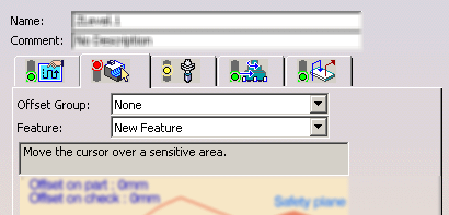
Offset Group Dialog Box
- Offset Global in the upper part of the
dialog box is the overall offset
that will be applied to the group in general.
However, it is applied only to offset areas in the offset group that do not have their own specific offset.

- Offset Local in the Create tab is a local offset
applied to specific areas.
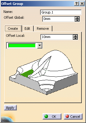
For example, let's consider a group with:
- an area that has a specific offset (Offset Local in the Create tab) of 10 mm and
- the remaining area that has no offset assigned to it (this is its original status).
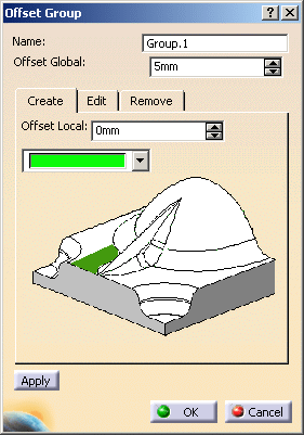
Apply an overall offset (Offset Global) of 5 mm to this group:
- the first area keeps its specific offset of 10 mm,
- whereas the 5 mm overall offset is applied to the second area.
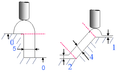
- The thickness of the offset can be negative.
If you want to use a negative value, the tool corner radius must be greater than the absolute value of the offset. - In the transition between faces with 2 different offsets, only the
bigger offset is taken into account.
- Offset groups can be used with all operations and rework areas.
If you are using a rework area that includes an offset group in an operation,
you will not be able to modify the offset group. - The same face cannot be used in two separate offset areas in the same
group.
If you wish to have two different offsets on any given face, you must create a new group for the second value.
this offset is added to the Offset Global of the offset group.
In our example above:
- on the first area, you will have the 10 mm Offset Local + the offset defined in the machining operation,
- on the second area, you will have the 5 mm Offset Global + the offset defined in the machining operation
-
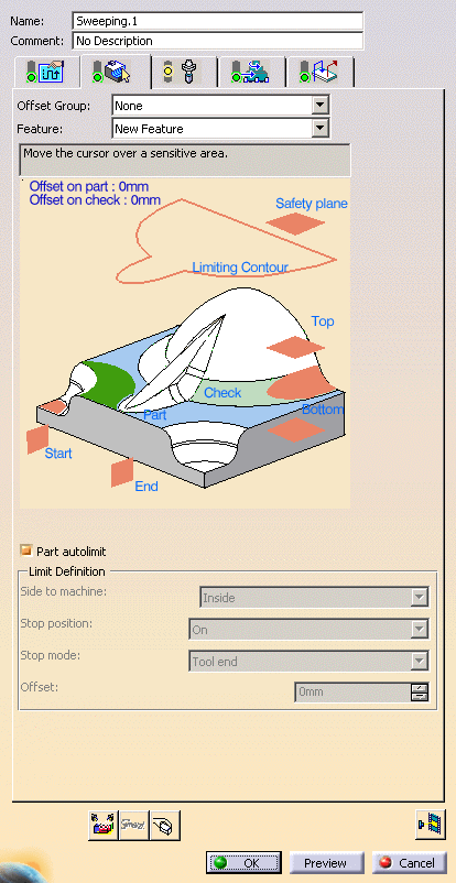
Open file Basic1.CATPart then select Machining > Surface Machining in the Start menu.
-
Apply a Sweeping to the whole part. This is what you get.
-
Exit the action by Cancel.

Note that no offset group is proposed as you enter the dialog box.
-
Click Offset Group
 .
.
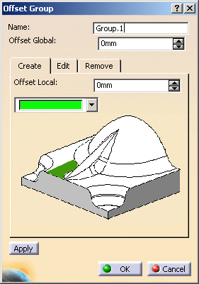
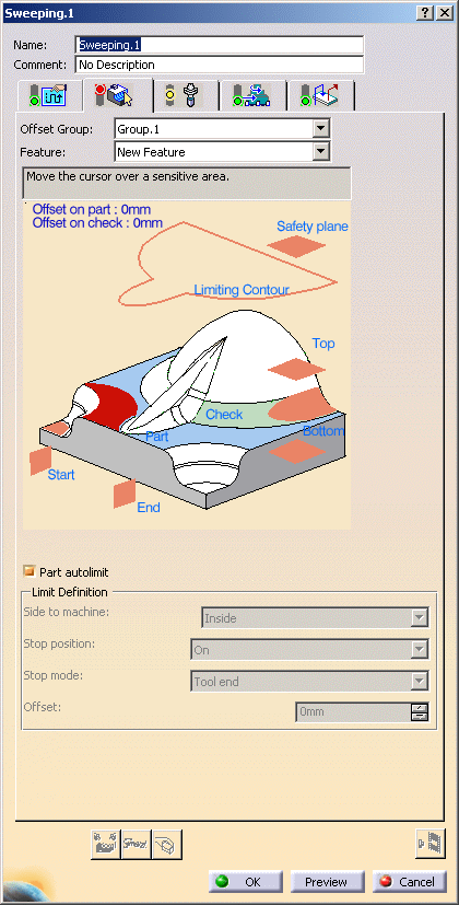
In the dialog box that is displayed, change the name of the group to Group.1.
-
Click the red area in the sensitive icon and
use the Face Selection Toolbar to select these three faces in the viewer.

-
Give the area that you have just created an Offset Local of 10 mm. Click Apply.
-
Now, without selecting any part nor face, enter an Offset Global of 5 mm.
Click OK.
-
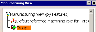
Open the Manufacturing view and you will see that the offset group has been created.
-
Now revert to the Sweeping dialog box.
Note that the Offset Group you have just created is proposed automatically. -
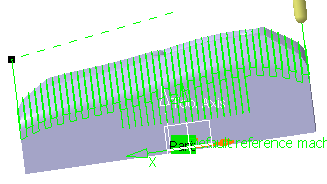
Select the part and click Tool Path Replay


you can see the difference with the first sweeping: -
Reduce the distance between pass and push Replay.
You can see that the offset applied to Offset Area.1 is different from that applied to the rest of the part:
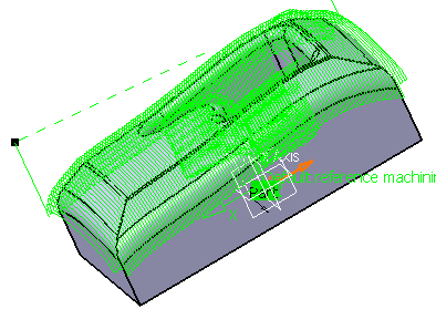
![]()
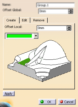
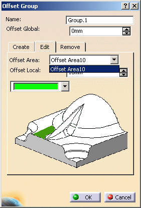
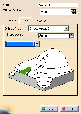
Editing an offset group
You can change the color, the offset or the contents of an offset area by selecting its name in the Edit tab.If you modify the offset value, the name of the Offset Area will not be updated to this new value.
-
Double-click Group.1 in the Manufacturing view.
-
Select Offset Area10 in the Edit tab.
-
Change the color to blue and the offset to 20.
Click OK.
-
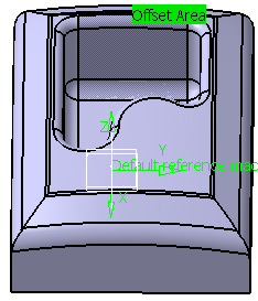
Go back into the Manufacturing view and double-lick the sweeping operation that you already computed.
Once it is displayed, click Tool Path Replay.
Compare the results with those above.
![]()
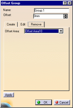
Deleting an offset area
-
In the Remove tab, select Offset Area10.
Click Apply.
Click OK to close the dialog box.
![]()