 |
-
Click Circular cutout
 in the Holes toolbar.
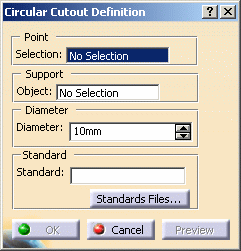
| The Circular cutout definition dialog box opens. |
 |
-
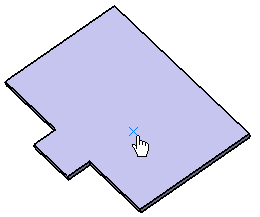
Select the Point that will be the center of
the circular cutout.
| It can be either a sketch containing one or more
points, or a point, or several points. The points must be on the
same support. |
 |
 |
-
The point can be
selected anywhere in the geometry, not necessarily on a surface.
In that case, an orthogonal projection will be performed.
-
You can also directly
click the surface: a point will be created under the pointer.
-
To deselect a point,
click it in the specification tree.
|
-
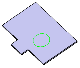
Select the Support object where the circular
cutout will be positioned (Wall.1 in our example).
|
|
The support can be different from the support where the point
lies. In that case, an orthogonal projection will be performed. |
| |
The cutout is previewed with default parameters. |
| |
 |
-
Define the value for the diameter of the circular
cutout in the Diameter field.
|
|
If you change the Diameter value using the spinners,
the preview of the circular cutout automatically updates. However,
if you enter a value directly in the field, you need to click the
Apply button to update the preview. |
-
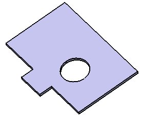
Click OK to validate.
| The circular cutout (identified as circular
cutout.xxx) is created and the specification tree is updated
accordingly. |
 |
|
|
Circular cutouts can be created on the
unfolded parts and on bends. |
 |
For further information on standard files, refer to the
Editing the Sheet and Tool Parameters. |
|