This task explains how to generate a swept flange from a spine and a user-defined profile.
If not, open the SweptWall04.CATPart document from the samples directory. As a profile is already defined on the part, you will be able to skip step 1 of the scenario.
![]()
-
If you are using the SweptWall01.CATPart document, click the Sketcher icon
 ,
and define a profile in the yz plane as shown below:
,
and define a profile in the yz plane as shown below:
Then quit the Sketcher, using the Exit icon
.
If you are using the SweptWall04.CATPart, go directly to step 2 as the profile is already defined.
-
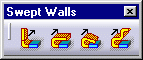
Select the Swept Flange icon
 in
the Swept Walls sub-toolbar.
in
the Swept Walls sub-toolbar.
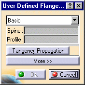
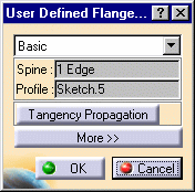
The User Defined Flange Definition dialog box opens.
-
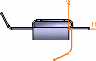
Select the edge and the profile, as shown in red.
The dialog box looks like this:
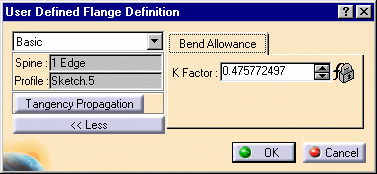
In this case, the new K Factor value overrides the value set in the Sheet Metal Parameters.
-
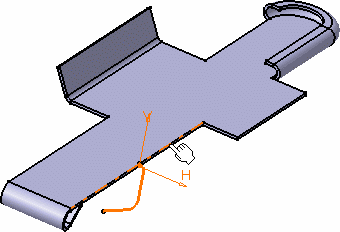
Click OK to create the swept flange.
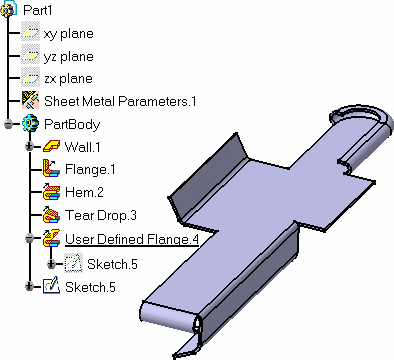
The feature is added in the specification tree.
- Use the Tangency Propagation button to select all tangentially contiguous edges forming the spine (see Selecting the Spine).
- You can redefine the hem limits by choosing the Relimited option (see Redefining Swept Walls Limits).
![]()