Split / Trim Surfaces

How to create a split or a trim surface when input elements are tangent to each other?
How to create a split or a trim surface when the input elements do not intersect each other?


How to create a split or a trim surface when input elements are tangent to each other?

Splitting a surface by another surface one requires the computation of the surface intersection. When the surfaces to be intersected are tangent, there are ways to avoid intersections.
Whenever possible, intersections and input elements that are tangent to each other should be avoided.
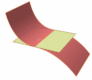
Similarly, the following cases should be avoided when possible (especially when the tangency constraint between the two surfaces has not been clearly defined by the user during the surface creation), as the result of the positioning is likely to be indeterminate and the result of the intersection to be unstable in the tangency zone.


Example 1

Two boundaries are in contact.

Workaround

  • Use the Join command between the two surfaces.
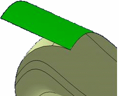
Example 2

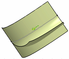
One portion of the surface is to be removed.

Workaround

  1. Extract the sweep boundary which is located on the extruded surface.
  2. Use the Extract result to split the extruded surface
  3. Join the swept surface and the split result.
Example 3

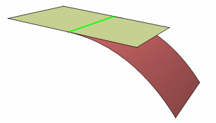
Surfaces are tangent or intersect face edges.

Workaround

In this case, use the border edge of the cutting surface to split the element to cut:
  1. Delimit the boundary of the cutting surface,
  2. Project this boundary onto the surface to split,
  3. Use this projection as the cutting element.
    The last two steps may be optional if the tangency constraint between the two surfaces has been clearly defined by the user during the surface creation.
How to create a split or a trim surface when the input elements do not intersect each other?

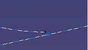
In the example below, the distance between the circle and the line is greater than the resolution but less than 0.01mm. There is a way to trim the line and obtain a result with no gap.

Workaround

  1. Project the point (liable not to be on the wire to be trimmed) on the line.
  2. Use the projected point as the splitting element.
  3. Join the circle wire with the split line and specify a merging distance value of 0.01 mm. If you do not use this option, you get two cells.
 
For more details about split surfaces, refer to Splitting Geometry; for trimmed surfaces, refer to Trimming Geometry.