Open the Sweep1.CATPart document.
With reference surface
![]()
-
Click Sweep
 .
.The Swept Surface Definition dialog box appears. -
Click the Explicit profile icon and select With pulling direction from the Subtype drop-down list.

It is not mandatory that the profile be a sketch. 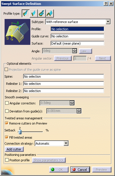
-
Select the Profile to be swept out (DemoProfile1).
-
Select a Guide curve (DemoGuide1).
-
Select a surface (by default, the reference surface is the mean plane of the spine) in order to control the position of the profile during the sweep.
-
If needed, select a Spine.
If no spine is selected, the guide curve is implicitly used as the spine.
Here is an example with DemoGuide2.
If a plane normal to the spine intersects one of the guiding curves at more than one points, the application chooses the closest point to the spine point. 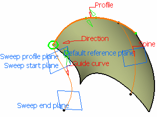
-
Click OK to create the swept surface.
The surface (identified as Sweep.xxx) is added to the specification tree.
With two guide curves
-
Click Sweep
 .
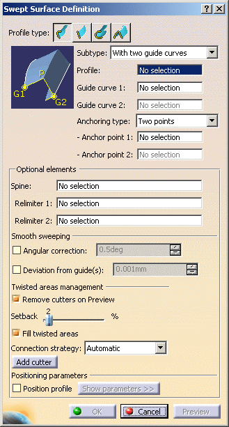
.The Swept Surface Definition dialog box appears. -
Click the Explicit profile icon and select With with two guide curves from the Subtype drop-down list.
-
Select the Profile to be swept out (DemoProfile1).
-
Select a first Guide curve (DemoGuide1).
-
Select a second Guide curve (DemoGuide2).
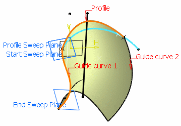
You can also specify anchor points for each guide. These anchor points are intersection points between the guides and the profile's plane or the profile itself, through which the guiding curves will pass. There are two anchoring types: - Two points: select anchor points on the profile that will be
matched respectively to Guide Curve 1 and 2.
These points must belong to the sweeping plane of the profile.
If the profile is open, these points are optional and the extremities of the profile are used.

- Point and direction: select an anchor
point on the profile which will be matched onto Guide Curve 1 and
an anchor direction.
In each sweeping plane, the profile is rotated around the anchor point so that the anchor direction (linked to this profile) is aligned with the two guide curves, from Guide Curve 1 to Guide Curve 2.
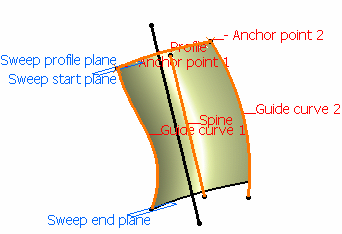
Sweep without positioning
Two points anchoring type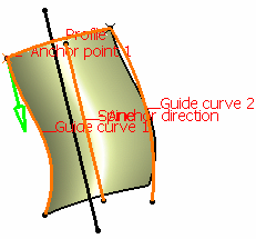
Sweep without positioning
Point and direction anchoring typeIf the profile is manually positioned defining anchor points will position the profile between the guides, matching the anchor points with guide intersection points, prior to performing the sweeping operation. 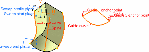
If you do not explicitly select anchor points or anchor direction, they are automatically computed if the profile is planar. Note that the selection is still available. The anchor points are computed as follows: - for Anchor point 1: intersection between the profile plane and Guide curve 1 (I1).
- for Anchor point 2: intersection between the plane, passing through Anchor point 1 and normal to the spine, with Guide curve 2 (I2).
- for Anchor direction: line between I1 and I2

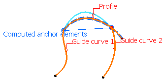
Automatic computation for Two points anchoring type 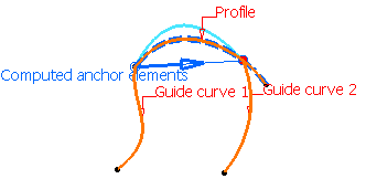
Automatic computation for Point and direction anchoring type
- Two points: select anchor points on the profile that will be
matched respectively to Guide Curve 1 and 2.
These points must belong to the sweeping plane of the profile.
-
If needed, select a Spine.
If no spine is selected, the guide curve is implicitly used as the spine.
Here is an example with DemoGuide2.
If the plane normal to the spine intersects one of the guiding curves at different points, it is advised to use the closest point to the spine point for coupling. 
-
Click OK to create the swept surface.
The surface (identified as Sweep.xxx) is added to the specification tree.
With pulling direction
-
Click Sweep
 .
.The Swept Surface Definition dialog box appears. -
Click the Explicit profile icon and select With pulling direction from the Subtype drop-down list.
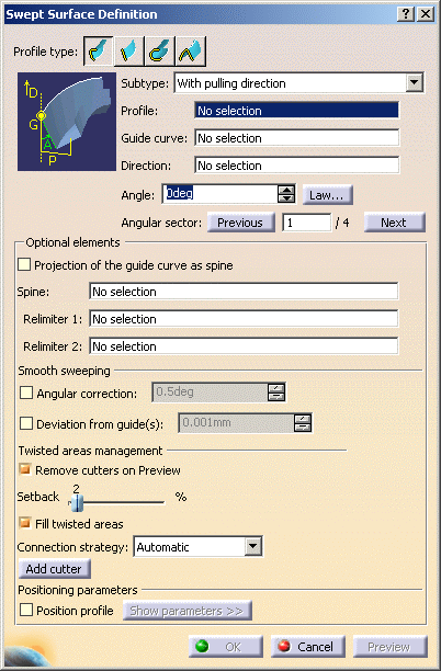
-
Select the Profile to be swept out (DemoProfile2).
-
Select a first Guide curve (DemoGuide1).
-
Select a Direction (zx plane).
-
Optionally, you can impose an Angle.
-
If needed, select a Spine.
If no spine is selected, the guide curve is implicitly used as the spine.
Here is an example with DemoGuide2.
If the plane normal to the spine intersects one of the guiding curves at different points, it is advised to use the closest point to the spine point for coupling. 
-
Click OK to create the swept surface.
The surface (identified as Sweep.xxx) is added to the specification tree.
Previewing The Angular Value
This option is not available with the With two guides curves subtype.
Optional Elements
Positioning Parameters
-
You can then directly manipulate the profile using the graphic manipulators in the geometry or access positioning parameters clicking Show Parameters>>.
-
These parameters allow you to position the profile in the first sweep plane. 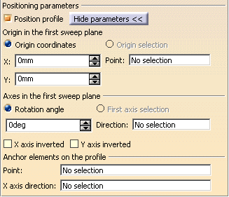
- Specify a positioning point in the first sweep plane by either entering coordinates or selecting a point.
- Specify the x-axis of the positioning axis system by either selecting a line or specifying a rotation angle.
- Select the X-axis inverted check box to invert the x-axis orientation (while keeping the y-axis unchanged).
- Select the Y-axis inverted check box to invert the y-axis orientation (while keeping the x-axis unchanged).
- Specify an anchor point on the profile by selecting a point. This anchor point is the origin of the axis system that is associated with the profile.
- Specify an axis direction on the profile by selection a direction. If no anchor direction was previously defined, the x-axis of the positioning axis system is used to join the extremities of the profile. The x-axis is aligned with the reference surface.
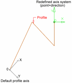
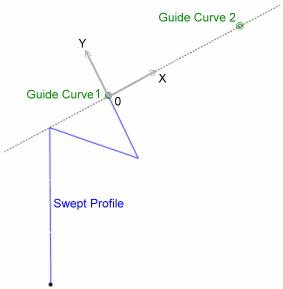
Reference Surface Two Guides If you want to go back to the original profile, deselect Position profile. 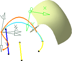
![]()
