To create a stiffener using a curve as a support, see Creating a Stiffener Using a Curve as a Support.


|
|
This task explains creation of a stiffener along
a plane.
To create a stiffener using a curve as a support, see Creating a Stiffener Using a Curve as a Support. |
|
|
|
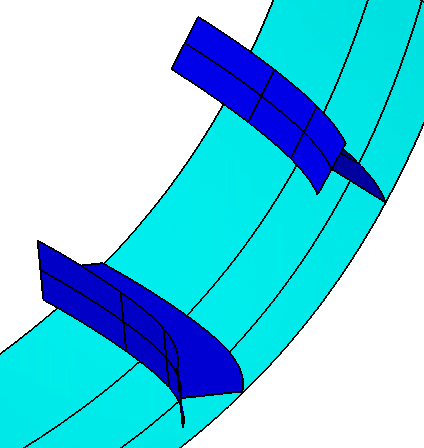
When a stiffener is created using the Along Plane
option, it retains the angle of the support that was selected. Stiffeners
created using the Normal to Plate option have an angle that is
normal to the plate they are on. Shell stiffeners are often created using
the Along Plane option. The image below shows two stiffeners
placed on a shell, which was created using a horizontal deck plane. The
one above is normal to the plate. The lower one has been placed using the
Along Plane option.
|
|
|
|
1. | With your
document open, click the Stiffener button
|
| 2. | Make your selections as described in Creating a Deck Longitudinal Stiffener or Creating a Deck Transverse Stiffener. | |
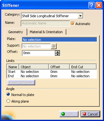
| 3. | The Angle options become available after you select a support. Select the Along Plane option to view what the stiffener looks like when this option is selected. You can toggle between the two Angle options. | |
| 4. | Click OK when you are finished. | |
![]()