Creating a Stiffener Using a Curve as a Support
|
|
This task explains how to create a stiffener using a curve as a support. | |
|
|
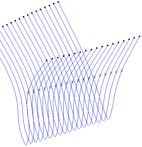
The technique used here requires you to draw a spline on the surface, and create the stiffener using it. You can also use a line as long as it is placed on the surface. The result shown here was produced using the Generative Shape Design (GSD) application. However, you can use other methods. To use GSD, you need to see documentation for that product. However, certain general principles are explained below. |
|
|
|
1. | In this example, the user wanted
to create a stiffener located at a certain distance below the top edge
of the hull - say 10 meters.
Using GSD, the user:
|
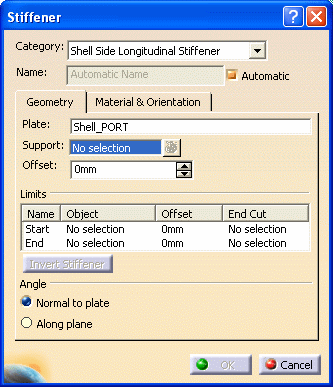
| 2. | After you have created the spline,
open the Object Design workbench. Select the hull
and click the Stiffener button. The Stiffener dialog box displays.
|
|
| 3. | Make the appropriate selection in the Category field, in this case Shell Side Longitudinal Stiffener. | |
| 4. | Select the shell plate in the Plate field. | |
| 5. | Select the spline in the Support field. | |
| 6. | Make your selections in the other
fields as described in Creating a Deck
Longitudinal Stiffener or Creating a Deck Transverse
Stiffener. NOTE: Although the Offset and Angle fields are available when creating a stiffener on a curve, neither affects the result. A stiffener on a curve is always created with an Offset of 0, and the angle is always Normal to Plate regardless of what the dialog box displays. When creating more than one stiffener at a time, if you select a mix of curve and plane for supports, the Offset and Angle fields are available, but ignored for stiffeners on a curve. If the Offset is changed to a non-zero value on a stiffener on a curve during edition, the operation will be ignored, and a warning is shown. |
|
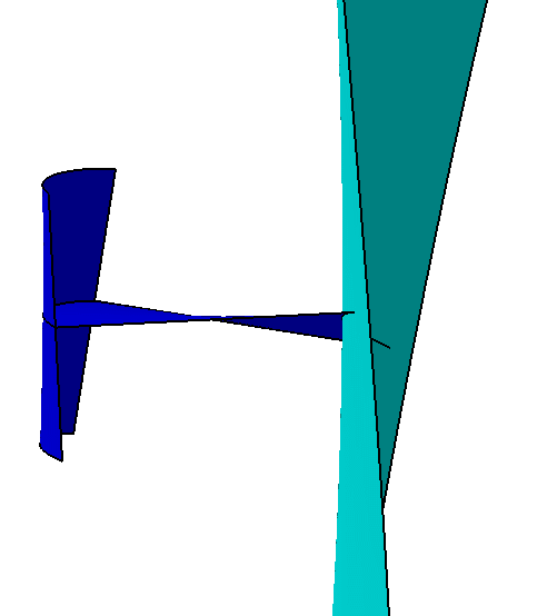
| 7. | Click OK to create the
stiffener. The image below shows a section of the hull with the
stiffener placed on it. The hull has been angled to allow you to see the
curvature of the stiffener.
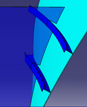
The image below shows two stiffeners placed on a hull.
|
|
![]()


